3 100base-tx system, 1 ) example using a switching hub, 2 ) example using a repeater hub – Yaskawa JAPMC-MC2303-E User Manual
Page 70
5
Details of FL-net
5.1 Ethernet Segment Configuration Example
5.1.3 100BASE-TX system
5-3
5.1.3 100BASE-TX system
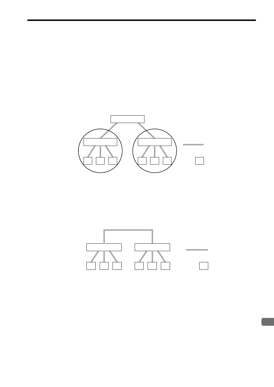
( 1 ) Example Using a Switching Hub
The system is generally called “Fast Ethernet,” supporting a baud rate of 100 Mbps. Generally, the 100BASE-TX sys-
tem employs a twisted pair cable for connection via a switching hub. The maximum length of each twisted pair cable is
100 m and is identical to that of 10BAESE-T system.
The switching hub serves as a bridge. When segments are connected via the switching hub, the cascade connection
count of the repeater is cleared and cascade restrictions are removed unlike with a repeater hub.
In addition, some switching hubs support multiple baud rates such as 100BASE-TX and 10BASE-T. The use of these
switching hubs enables 100BASE-TX and 10BASE-T equipment in the same system.
In this case, however, care should be taken because the switching hub causes a greater delay than the repeater hub.
( 2 ) Example Using a Repeater Hub
When a 100BASE-TX repeater hub is used, it is subject to cascade connection restrictions. When a Class II repeater
hub has been used, a maximum of two cascade connections can be made for the repeater hub. In this case, however, the
maximum distance between repeater hubs is 5 m.
The following figure shows a system configuration example.
Switching hub
N
N
N
㧦Twisted pair cable
㧔100BASE-TX㧕
㧦Node
N
Switching hub
Switching hub
N
N
N
Segment
Segment
Repeater hub
N
N
N
㧦Twisted pair cable
㧔100BASE-TX㧕
㧦Node
N
Repeater hub
N
N
N