Appendix e differences from cp series/262if, A-23 – Yaskawa JAPMC-MC2303-E User Manual
Page 173
Appendix E Differences from CP Series/262IF
A-23
App
Appendices
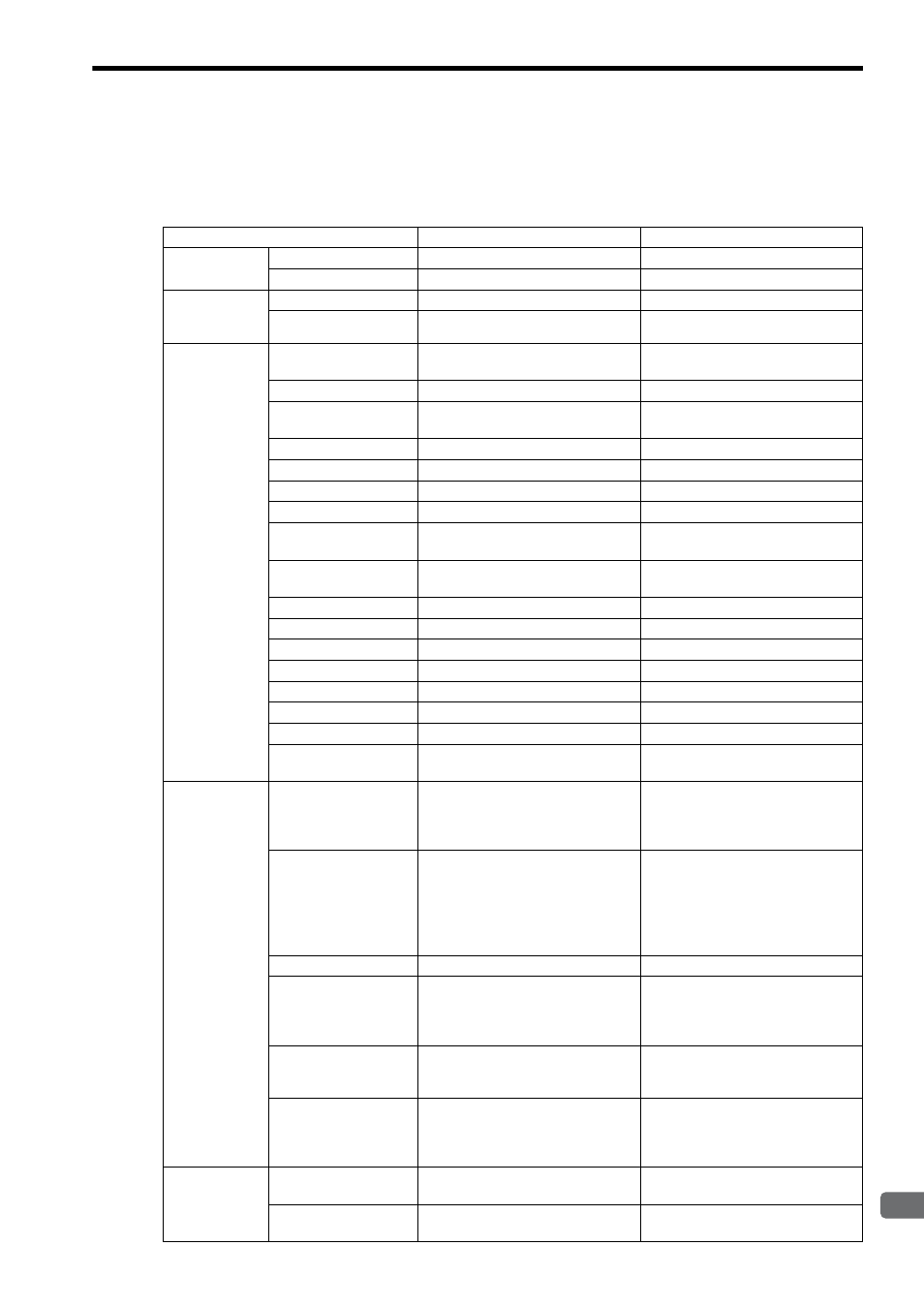
Appendix E Differences from CP Series/262IF
The following lists functional differences between our CP Series Controller FL-net Module (CP317/262IF) and MP
Series Machine Controller FL-net Module (262IF-01).
Item
262IF-01
CP317/262IF
Transmission
specifications
Interface
100BASE-TX, 10BASE-T
10BASE-T
Baud rate
100 Mbps/10 Mbps
10 Mbps
Link
transmission
specifications
Area 1 assignment size
0 to 512 words (total: 512 words)
0 to 512 words (total: 512 words)
Area 2 assignment size
0 to 8,192 words (total: 8192 words)
0 to 8,192 words (total: 8192 words)
Message
transmission
specifications
Number of message
channels
10
15
Message size
Up to 512 words
Up to 512 words
Engineering
communication
Not supported
Not supported
Byte block read
×
×
Byte block write
×
×
Word block read
{
{
Word block write
{
{
Network parameter
read
{
{
Network parameter
write
Allowed only for clients
Allowed only for clients
Stop command
Allowed only for clients
Allowed only for clients
Start command
Allowed only for clients
Allowed only for clients
Profile read
{
{
Transparent message
{
{
Log data read
{
{
Log data clear
{
{
Message loopback
{
{
Vendor-specific
message
×
×
Screen
specifications
Parameter setting
Node number, subnet mask, token
monitoring time, minimum allowable
frame interval, common memory size
setting, and node name
Node number, subnet mask, token
monitoring time, minimum allowable
frame interval, and node name
Link assignment
Assignment by common memory area
image
(An I/O register range is determined
automatically when the common
memory area address and size are
specified.)
Assignment by I/O register image
(I/O registers must be assigned in
units of nodes, and common memory
areas 1 and 2 within each node must
be assigned.)
I/O map
Not supported
Supported
Link status
The detailed contents of the upper layer
and FA link status can be displayed on
the Status Detail Window in units of
bits.
The upper layer and FA link status both
support HEX display only. Detailed
contents are not provided.
Status
No device version is displayed.
The manufacturer name and model are
displayed.
A device version is displayed.
The manufacturer name and model are
not displayed.
Network calibration
information read
The address and size of each of the
common memory areas 1, 2 and the
detailed contents of the upper layer and
FA link status are displayed.
Only the address and size of each of the
common memory areas 1, 2 are dis-
played.
Others
Number of network
nodes
254 (number of assignable nodes: 64)
254 (number of assignable nodes: 64)
Number of module
lines
8
8