Appendix c fl-net system grounding, C.1 overview, A-14 – Yaskawa JAPMC-MC2303-E User Manual
Page 164
Appendix C FL-net System Grounding
C.1 Overview
A-14
Appendix C FL-net System Grounding
C.1
Overview
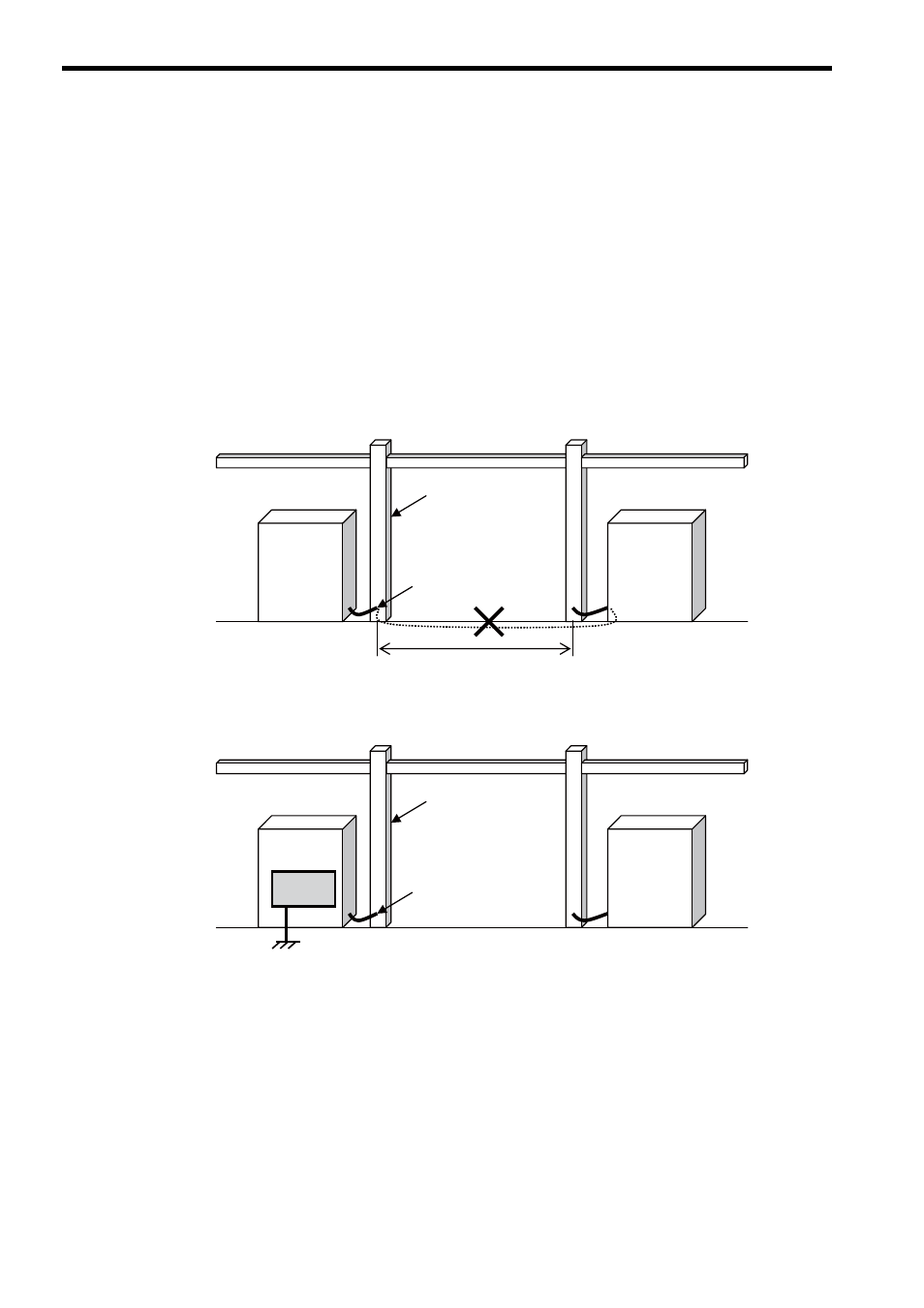
The following gives an example of grounding a control panel to the iron frame of a building to describe a method for
grounding the FL-net system controller control panel in Fig. C.1 and Fig. C.2.
When the control panel needs to be grounded to the iron frame of a building, the following requirements must be met.
When these requirements are not met, it must be subject to controller-dedicated grounding (ground resistance: 100
Ω or
less).
• The iron frames must be welded to each other.
• The ground and iron frame must be grounded with a ground resistance of 100
Ω..
• There can be no current flows into a ground point of the control panel from the power circuit.
• The distance between the ground point of the control panel and that of the magnetics panel must be at least 15
m.
Fig. C.1 Example 1 of Grounding a Controller Control Panel (Grounding on Iron Frames)
Fig. C.2 Example 2 of Grounding a Controller Control Panel
(Grounding Controller Alone with Ground Resistance of 100
Ω or less)
Control panel
Magnetics
panel
Iron frame of building
Iron frame grounding point
Distance: 15 m or more
Control panel
Magnetics
panel
Iron frame of building
Iron frame grounding point
PLC, etc.