2 appearance and connectors, 3 status indicators (leds) – Yaskawa JAPMC-MC2303-E User Manual
Page 25
2.1 Overview of 262IF-01 Module
2.1.2 Appearance and Connectors
2-6
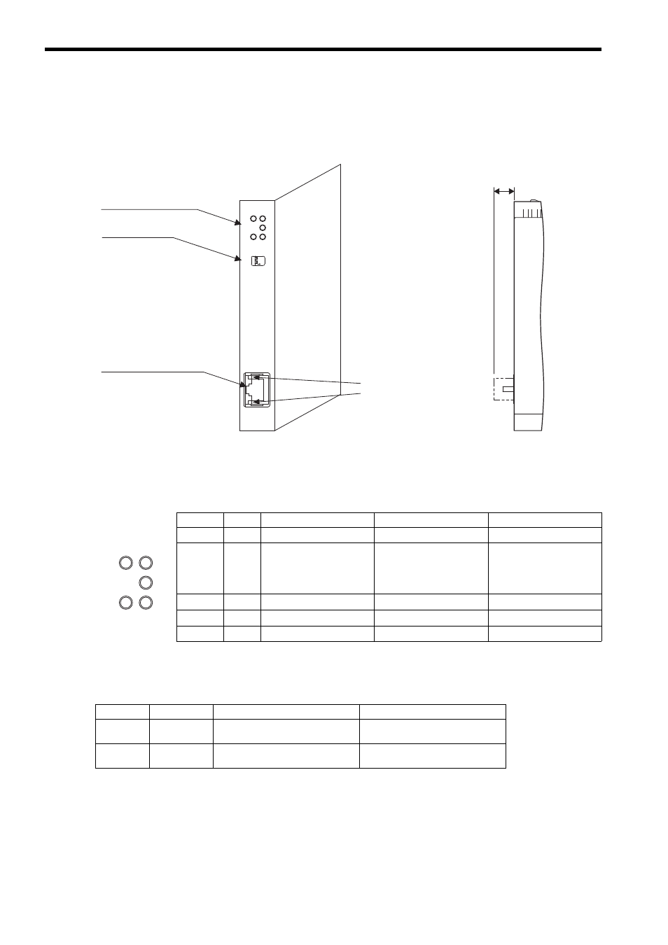
2.1.2 Appearance and Connectors
The following diagram shows the appearance of the 262IF-01 Module and gives the external dimensions of the connec-
tors.
2.1.3 Status Indicators (LEDs)
The following table shows the status of the 262IF-01 Module shown by the LED indicators.
2.1.4 Communication Status Indicators (LED) (Included with Ethernet Connector)
The indicators (LEDs) included with the Ethernet connector show the status of Ethernet communication.
262IF-01
ERR
LNK
RX
RUN
TX
-
TEST
ON
OFF
LINK
100M
FL-net
(25)
01
FL-net connector
100Base-TX/10Base-T
Status indicators
(LEDs)
Switches
Communication status
indicator (LED)
(included with connector)
Unit: mm
Indicator Color
Meaning When Lit
Meaning When Blinking
Meaning When Not Lit
RUN
Green Operating normally
–
An error has occurred.
ERR
Red
–
• When RUN is lit:
Parameter setting error
• When RUN is not lit:
Hardware error
Normal
LNK
Green Joining FL-net
–
Not joining FL-net
TX
Green Sending data
–
Not sending data
RX
Green Receiving data
–
Not receiving data
ERR
LNK
RX
RUN
TX
Indicator
Color
Meaning When Lit
Meaning When Not Lit
LINK
Yellow
FL-net link established.
FL-net link not established.
100M
Green
Green: 100 Mbps
10 Mbps or not connected