2 link assignment tab page, 1 ) details of the link assignment tab page – Yaskawa JAPMC-MC2303-E User Manual
Page 59
4.2 FL-net Transmission Definition
4.2.2 Link Assignment Tab Page
4-6
4.2.2 Link Assignment Tab Page
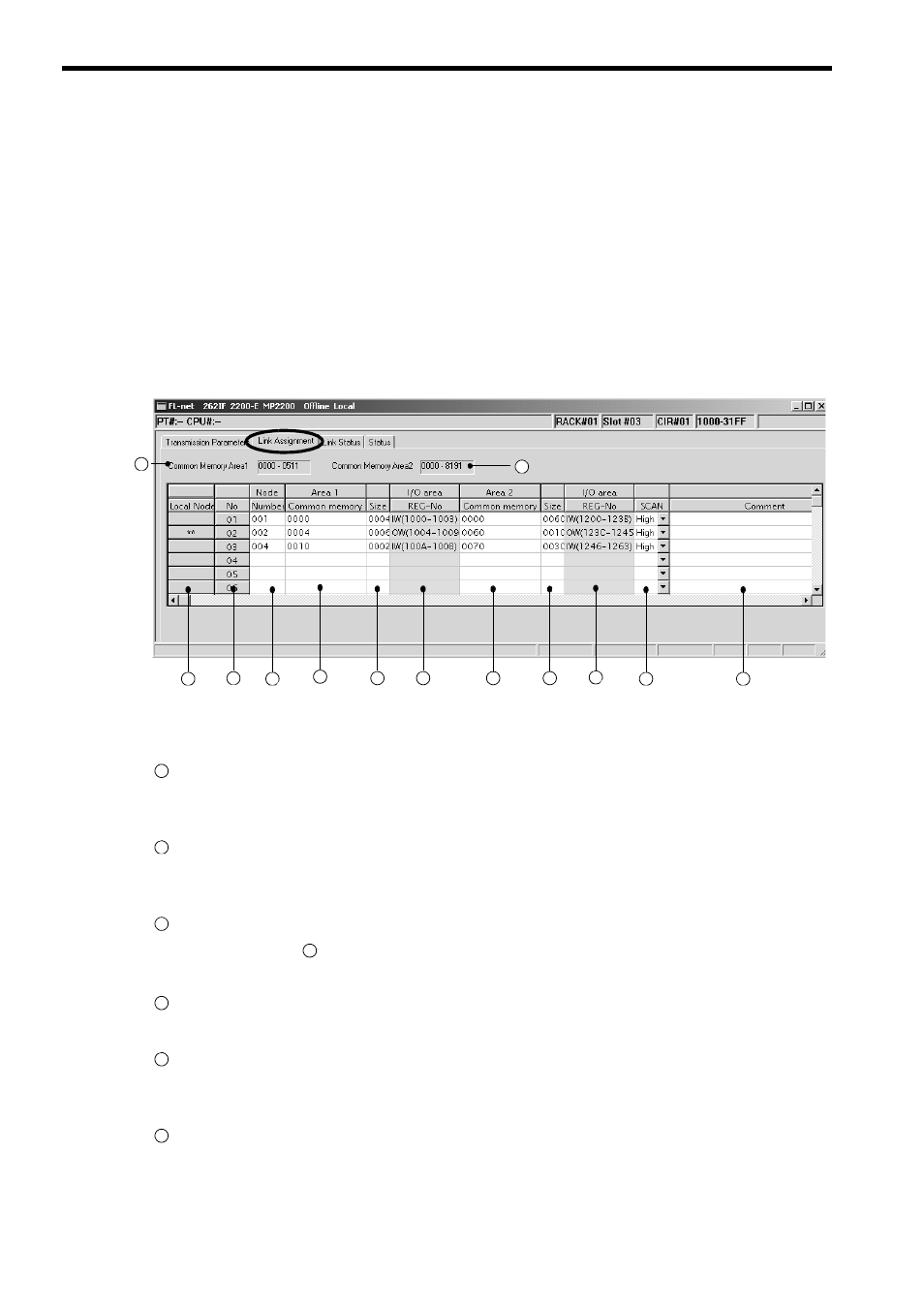
( 1 ) Details of the Link Assignment Tab Page
Set link assignment for each node in FL-net on the Link Assignment Tab Page.
Information on common memory areas 1 and 2 of each node, which has been received through cyclic transmission, is
stored in the registers of areas 1 and 2 of each node set here. In addition, information on common memory areas 1and 2
of a local node is broadcast to other nodes on FL-net when it holds the token.
Information on common memory areas 1 and 2 of other nodes, which is to be assigned here, must be identical to
that assigned to the nodes for themselves. To assign other nodes, assignment information must be obtained in
advance or the Network Configuration Window (refer to page 4-13) must be opened with the node joined to FL-net
to confirm the node information.
For the relationship between common memory area assignments to nodes and I/O registers, refer to 4.2.2 ( 3 ) Link
Assignment Setting Example and Common Memory Assignment Image on page 4-8.
The following gives a detailed description.
Common Memory Area 1
Displays the area 1 address range determined according to the setting of the transmission parameter Common
memory area 1 size on the Transmission Parameters Tab Page. This range cannot be changed.
Common Memory Area 2
Displays the area 2 address range determined according to the setting of the transmission parameter Common
memory area 1 size on the Transmission Parameters Tab Page. This range cannot be changed.
Local Node
When a node number (
) is identical to the least significant digit in IP address on the Transmission Parame-
ters Tab Page, “**” is displayed here to indicate a local node.
No.
Displays the interface number for CPU (fixed).
Node Number
Enter the node number (least significant digit in IP address) of a node to be assigned.
This value can be set in a range from 1 to 254. Note that the setting value must be unique.
Area 1 Common memory
Set the I/O leading register address of FL-net common memory area 1 of a target node for assignment in units of
words. This value can be set in a range from 0 to 511.
3
4
5
6
7
8
9
10
11
12
13
1
2
1
2
3
5
4
5
6