Yaskawa JAPMC-MC2303-E User Manual
Page 44
3.3 Setting the Communication Manager
3.3.2 Setting the Communication Manager
3-14
( 3 ) Setting the Ethernet (LP) Communication Port
These are the optimum settings to perform engineering via the Ethernet communication port of the 218IF-02 Module.
For Ethernet connection, a general-purpose Ethernet board or PCMCIA Ethernet card must be mounted on the personal
computer. Prior to make settings, the IP address of the personal computer must be set.
The Ethernet (LP) communication port can be connected to the 218IFB function of the 218IF-02 Module. It has a
larger engineering message size in comparison to previous Ethernet communication ports, enabling high-speed engi-
neering communication.
The port type and Modules that can be used together are given in the following table.
[ a ] Mounting an Ethernet Card
Mount a general-purpose Ethernet board or PCMCIA Ethernet card on the specified connector of the personal com-
puter. Also, install the driver provided with the Ethernet card.
[ b ] Setting the IP Address
Set the IP address of the person computer using the procedure given in 3.3.2 ( 2 ) [ b ] Setting the IP Address on page
3-11.
[ c ] Setting the Ethernet (LP) Communication Port
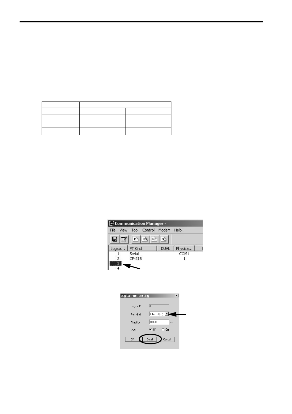
1.
Double-click Logical Port No. 3 in the Communication Manager Window to display the Logical Port
Setting Dialog Box.
2.
Select Ethernet (LP) under Port Kind in the Logical Port Setting Dialog Box and click the Detail But-
ton.
The CP-218/Ethernet (LP) Port Setting Dialog Box will be displayed.
Port Type
Module
218IF-01(218IF)
218IF-02(218IFB)
CP-218
{
{
Ethernet
{
{
Ethernet (LP)
×
{