6 network configuration window – Yaskawa JAPMC-MC2303-E User Manual
Page 66
4
FL-net T
ransmission
Definition
4.2 FL-net Transmission Definition
4.2.6 Network Configuration Window
4-13
4.2.6 Network Configuration Window
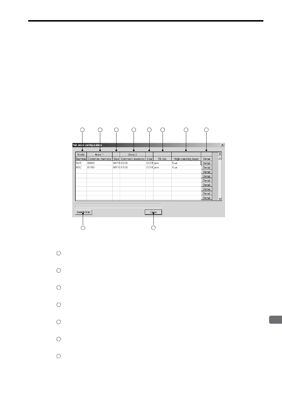
The status of all nodes connected to FL-net can be monitored on the Network Configuration Window.
( 1 ) Displaying the Network Configuration Window and
Searching for the Statuses of the Connected Nodes
Select Edit - Network configuration from the Main Menu to display the Network Configuration Window.
Network configuration under the Edit menu is enabled only in Online Mode.
Click the Search Start Button on the Network Configuration Window to display the statuses of all nodes connected
to FL-net.
Click the Close Button to close the Network Configuration Window.
( 2 ) Displayed Contents of the Network Configuration Window
The following gives a detailed description.
Node Number
Displays the node number of FL-net equipment.
Area 1 Common memory
Displays the address number of common memory area 1 occupied by the node.
Size (area 1 size)
Displays the register size of common memory area 1 occupied by the node in units of words.
Area 2 Common memory
Displays the address number of common memory area 2 occupied by the node.
Size (area 2 size)
Displays the register size of common memory area 2 occupied by the node in units of words.
FA link
Displays the current status whether the node joins or leaves FL-net as “Join” or “Leave.”
High-ranking layer (Upper layer RUN/STOP)
Displays the bit 7 RUN/STOP status of the FL-net upper layer status as “RUN” or “Stop.”
9
1
2
3
4
5
6
7
8
10
1
2
3
4
5
6
7