4 parameter list for msg-rcv function – Yaskawa JAPMC-MC2303-E User Manual
Page 108
6
Message Send and Receive Functions
6.2 Message Receive Function
6.2.4 Parameter List for MSG-RCV Function
6-23
6.2.4 Parameter List for MSG-RCV Function
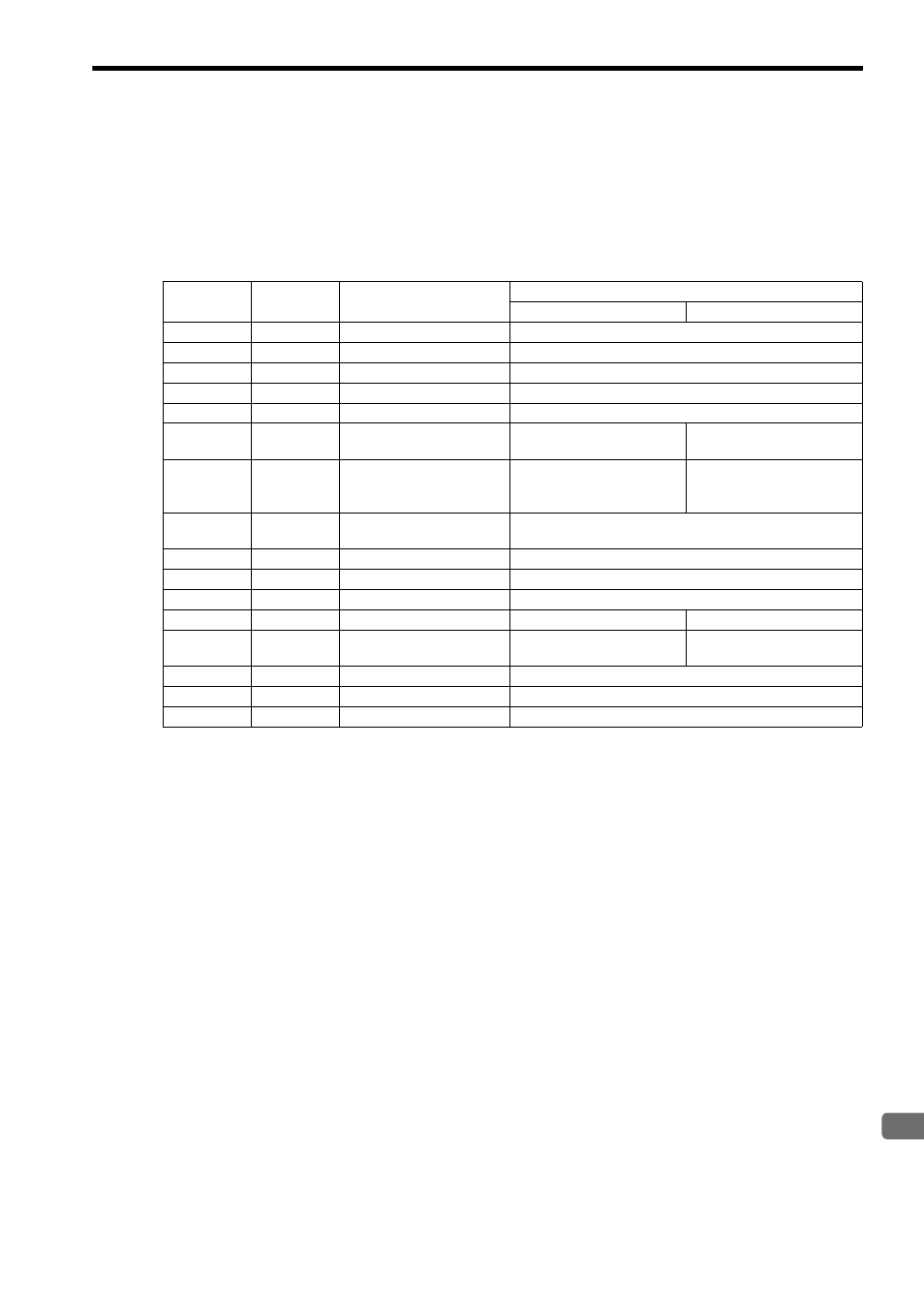
The Param input to the MSG-RCV function is a parameter list structure consisting of 17 words. The value of the Param
input is the leading address (MA or DA) of the parameter list.
Use the parameter list to input the holding register offset value and write range LO/HI. The processing results and con-
nection number are also output to the parameter list.
The parameter lists for the MEMOBUS and non-procedure communication protocols in FL-net are given below.
IN: Input, OUT: Output, SYS: Used by the system.
Refer to 6.2.5 Parameter Details for MSG-RCV Function on page 6-24 for details on the parameters.
PARAM No.
IN/OUT
Contents
Description
Pro-Typ=1 (MEMOBUS)
Pro-Typ=2 (Non-procedure)
00
OUT
Processing result
The processing results are output here.
01
OUT
Status
The status of the current MSG-RCV function is output here.
02
OUT
Remote node number
The source node number (1 to 254) is output here.
03
SYS
Reserved by the system (1).
04
OUT
Function code
Not used.
05
OUT
Data address
The data address is output
here.
Not used.
06
OUT
Data size
The data size is output here.
The data size is output here.
The first one word of the data
is a transaction code.
07
OUT
Remote CPU number
(address upper word)
0 is output here.
08
IN
Coil offset
Not used.
09
IN
Input relay offset
Not used.
10
IN
Input register offset
Not used.
11
IN
Holding register offset
Register offset
Not used.
12
IN
Write range LO/ holding
register offset
The lower value of write range The register offset
13
IN
Write range HI
The upper value of write range
14
SYS
Reserved by the system (2).
15 and 16
SYS
Reserved by the system (3).