Yaskawa Sigma II Series DC Power Input SGMAJ User Manual
Page 327
10 Inspection, Maintenance, and Troubleshooting
10.4.2 List of Parameters
10-46
* 1. Normally set to “0.” When using an external regenerative resistor, set the allowable power loss (W)
of the regenerative resistor.
* 2. The upper limit is the maximum output capacity (W) of the SERVOPACK.
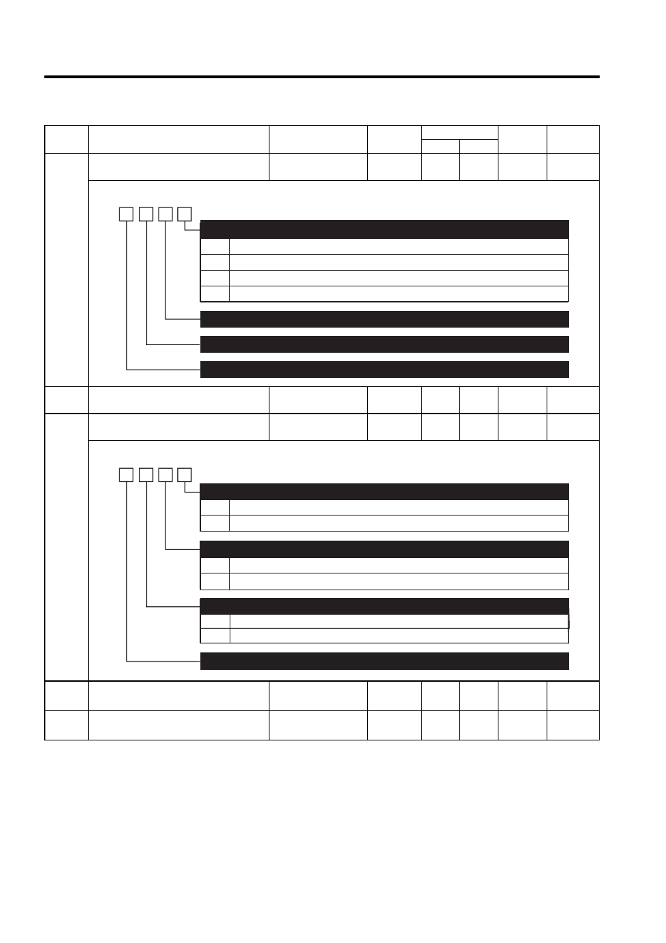
Pn510
Output Signal Selections 3
0000 to 0333
−
0000
0000
After
restart
−
Pn511
Reserved (Do not change)
−
−
8888
8888
Immedi-
ately
−
Pn512
Output Signal Reversal Settings
−
−
0000
0000
After
restart
7.3.3
Pn600
Regenerative Resistor Capacity
∗1
Depends on SERVO-
PACK Capacity
∗2
10 W
0
0
Immedi-
ately
−
Pn601
Reserved (Do not change)
Depends on SERVO-
PACK Capacity
∗2
−
0
0
Immedi-
ately
−
Parame-
ter No.
Name
Setting Range
Units
Factory Setting
Setting
Validation
Reference
Section
S P
0
1
2
3
Disabled (the above signal is not used.)
Outputs the signal from CN1-25 or -26 terminals.
Outputs the signal from CN1-27 or -28 terminals.
Outputs the signal from CN1-29 or -30 terminals.
Near Signal Mapping (/NEAR)
(Refer to "8.6.6 Positioning Near Signal.")
4th
digit
3rd
digit
2nd
digit
1st
digit
n.
Reserved (Do not change)
Reserved (Do not change)
Reserved (Do not change)
0
1
0
1
0
1
Output signal is not reversed.
Output signal is reversed.
Output signal is not reversed.
Output signal is reversed.
Output signal is not reversed.
Output signal is reversed.
Output Signal Reversal for CN1-8 or -10 Terminals
4th
digit
3rd
digit
2nd
digit
1st
digit
n.
Output Signal Reversal for CN1-9 or -10 Terminals
Output Signal Reversal for CN1-7 or -10 Terminals
Reserved (Do not change)