Yaskawa Sigma II Series DC Power Input SGMAJ User Manual
Page 296
10.1 Troubleshooting
10-15
10
Servomotor
Vibrates at
about 200 to
400 Hz
Speed loop gain value (Pn100) too
high.
Factory setting: Kv=40.0 Hz
Refer to 9.3.2 Servo Gain Manual Tuning.
Reduce speed loop gain (Pn100) preset value.
Position loop gain value (Pn102) too
high
Factory setting: Kp=40.0/s
Refer to 9.3.2 Servo Gain Manual Tuning.
Reduce position loop gain (Pn102) preset value.
Incorrect speed loop integral time
constant (Pn101) setting
Factory setting: Ti=20.00 ms
Refer to 9.3.2 Servo Gain Manual Tuning.
Correct the speed loop integral time constant (Pn101)
setting.
When the autotuning is used: Incor-
rect machine rigidity setting
Check the machine rigidity setting (Fn001).
Select a proper machine rigidity setting (Fn001).
When the autotuning is not used:
Incorrect rotational moment of iner-
tia ratio data
Check the rotational moment of inertia ratio
data (Pn103).
Correct the rotational moment of inertia ratio data
(Pn103).
High
Rotation
Speed
Overshoot on
Starting and
Stopping.
Speed loop gain value (Pn100) too
high
Factory setting: Kv=40.0 Hz
Refer to the gain adjustment in User’s Man-
ual.
Reduce the speed loop gain (Pn100) preset value.
Position loop gain value (Pn102) too
high
Factory setting: Kp=40.0/s
Refer to the gain adjustment in User’s Man-
ual.
Reduce the position loop gain (Pn102) preset value.
Incorrect speed loop integral time
constant (Pn101) setting
Factory setting: Ti=20.00 ms
Refer to the gain adjustment in User’s Man-
ual.
Correct the speed loop integral time constant (Pn101)
setting.
When the autotuning is used: Incor-
rect machine rigidity setting
Check the machine rigidity setting (Fn001).
Select a proper machine rigidity setting (Fn001).
When the autotuning is not used:
Incorrect rotational moment of iner-
tia ratio data
Check the rotational moment of inertia ratio
data (Pn103).
Correct the rotational moment of inertia ratio data
(Pn103).
Use the mode switch setting function.
Absolute
Encoder
Position
Difference
Error
(The position
saved in host
controller
when the
power turned
OFF is differ-
ent from the
position when
the power
turned ON.)
Noise interference due to improper
encoder cable specifications
The specifications of encoder cable must
be:
Twisted-pair or twisted-pair shielded wire
with core 0.12 mm
2
(0.0002 in
2
) min. and
tinned annealed copper twisted wire.
Use encoder cable with the specified specifications.
Noise interference because the
encoder cable distance is too long.
The wiring distance must be 20 m (65.6 ft)
max.
The encoder cable distance must be within the specified
range.
Noise interference due to damaged
encoder cable
Noise interference occurred to the signal
line because the encoder cable is bent or its
sheath damaged.
Correct the encoder cable layout.
Excessive noise to the encoder cable
Check if the encoder cable is bundled with a
high-current line or near high-current line.
Change the encoder cable layout so that no surge is
applied.
FG electrical potential varies by
influence of such machines on the
servomotor side as welder.
Check if the machine is correctly grounded.
Ground the machine separately from PG side FG.
SERVOPACK pulse counting error
due to noise interference
Check if the signal line from the encoder
receives influence from noise interference.
Take measures against noise for encoder wiring.
Excessive vibration and shock to the
encoder
Vibration from machine occurred or servo-
motor mounting such as mounting surface
precision, fixing, and alignment is incor-
rect.
Reduce vibration from machine or mount securely the
servomotor.
Encoder fault
An encoder fault occurred. (no change in
pulse count)
Replace the servomotor.
SERVOPACK fault
Check the multiturn data from SERVO-
PACK.
Replace the SERVOPACK.
Host controller multiturn data read-
ing error
Check the error detection at the host con-
troller.
Correct the error detection section of host controller.
Check if the host controller executes data
parity check.
Execute the multiturn data parity check.
Check noise on the signal line between
SERVOPACK and the host controller.
Noise influence at no parity check (as the above.)
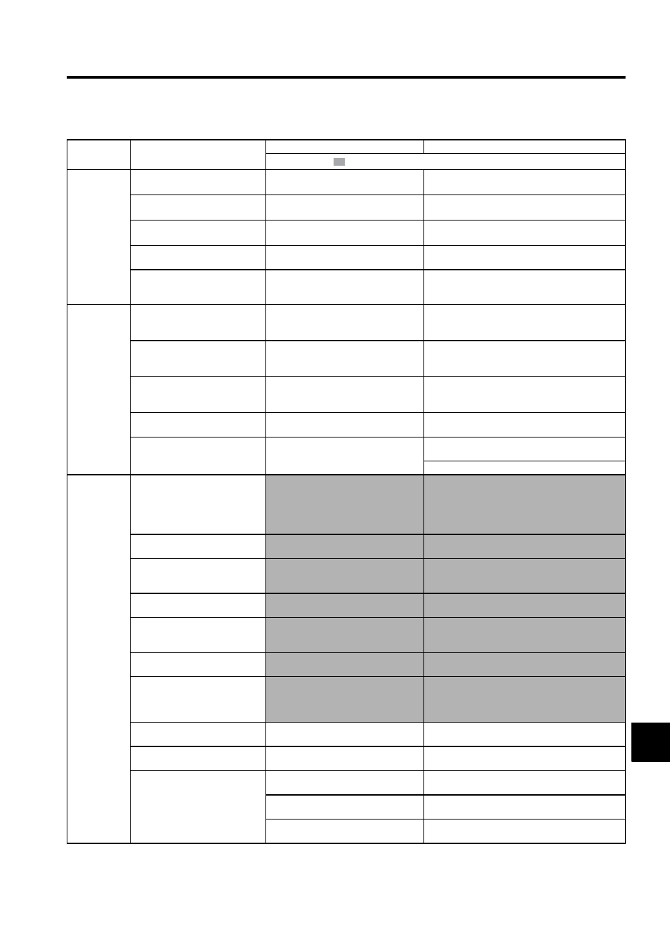
Table 10.5 Troubleshooting for Malfunction without Alarm Display (cont’d)
Symptom
Cause
Inspection
Corrective Actions
: Turn OFF the servo system before executing operations.