1 troubleshooting, 1 alarm display table – Yaskawa Sigma II Series DC Power Input SGMAJ User Manual
Page 283
10 Inspection, Maintenance, and Troubleshooting
10.1.1 Alarm Display Table
10-2
10.1 Troubleshooting
10.1.1 Alarm Display Table
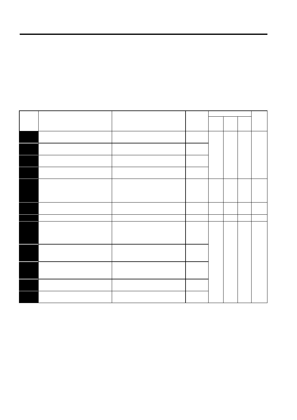
The relation between alarm displays and alarm code outputs is shown in Table 10.1.
If an alarm occurs, the servomotor can be stopped by doing either of the following operations.
• DB STOP: Stops the servomotor immediately using the dynamic brake.
• ZERO-SPEED STOP: Stops the servomotor by setting the speed reference to “0.”
Table 10.1 Alarm Displays and Outputs
Alarm
Display
Alarm Name
Meaning
Alarm
Reset
Alarm Code Output
Servo
Alarm
(ALM)
Output
ALO1
ALO2
ALO3
A.02
Parameter Breakdown
EEPROM data of SERVOPACK is
abnormal.
N/A
H
H
H
H
A.03
Main Circuit Encoder Error
Detection data for power circuit is
abnormal.
Available
A.04
Parameter Setting Error
The parameter setting is outside the
allowable setting range.
N/A
A.05
Combination Error
SERVOPACK and servomotor capaci-
ties do not match each other.
Available
A.10
Overcurrent or Heat Sink Overheated
An overcurrent flowed through the
IGBT.
Heat sink of SERVOPACK was over-
heated.
N/A
L
H
H
H
A.40
Overvoltage
Main circuit DC voltage is excessively
high.
Available
H
H
L
H
A.51
Overspeed
The motor speed is excessively high.
Available
L
H
L
H
A.71
Overload: High Load
The motor was operating for several
seconds to several tens of seconds
under a torque largely exceeding rat-
ings.
Available
L
L
L
H
A.72
Overload: Low Load
The motor was operating continuously
under a torque largely exceeding rat-
ings.
Available
A.73
Dynamic Brake Overload
When the dynamic brake was applied,
rotational energy exceeded the capac-
ity of dynamic brake resistor.
Available
A.74
Overload of Surge
Current Limit Resistor
The main circuit power was frequently
turned ON and OFF.
Available
A.7A
Heat Sink Overheated
The heat sink of SERVOPACK over-
heated.
Available