Interpretation, Tieline drawing page – Grass Valley NV9000 Web Suite v.1.2 User Manual
Page 93
83
NV9000 Web Suite
User’s Guide
The numbers in parentheses in the tieline field are the NV9000 database IDs for the entries in
those fields. (The presence of these numbers is a page configuration option.)
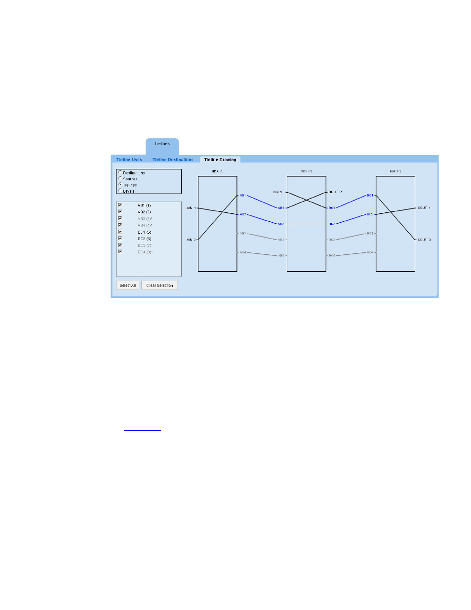
Tieline Drawing Page
The ‘Tieline Drawing’ page presents a graphical view of tielines used for routes:
Fig. 4-5: Tieline Drawing Page
At the left side of the page are controls (radio buttons and check boxes) that let you select for
display only the items you want to see.
The radio buttons select the category of items that you can choose in the section of check boxes
below the radio buttons. If you click the ‘Destinations’ radio button, the check boxes correspond
to destinations related to the tielines.
By checking and unchecking the items (such as destinations) in the check box list, you can
control which tielines are shown in the drawing.
In Figure 4-5 above, the ‘Tielines’ radio button was chosen. Therefore, the names of tielines
appear in the checkbox list. In this case, all check boxes are selected. The drawing includes
unused tielines. (To include or exclude unused tielines is a a tieline preference that you can set.
See
, following)
There are two buttons below the check box list: ‘Select All’ and ‘Clear Selection’. These are short-
cuts that allow you to select all check boxes in the list or unselect all check boxes in the list.
Interpretation
Figure 4-5 shows a drawing representing the tieline example of Figure 4-2.
Each rectangle represents a physical level of a router. The rectangles are labeled with the level
name (which is defined in NV9000-SE Utilities). In many cases, a router has a single physical level,
so in those cases, the rectangle represents the router as well.