Notes, Connectors, Button panel – Grass Valley iMC-Panel-100 v.7.0.9.0 User Manual
Page 48: Power, Control panel
36
Rev 1.0 • 29 Nov 11
3. Control Panel
Connectors
Notes
Remember that most of the iMC-Panel-100’s button legends are at the discretion of the configurer.
They might not be exactly what you see listed in this guide.
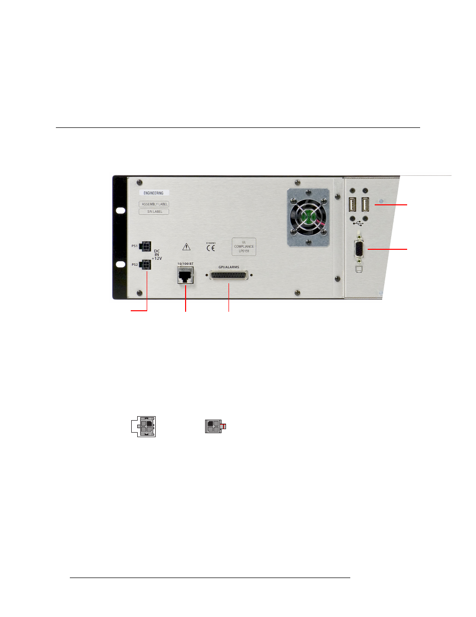
Connectors
At the rear of the iMC-Panel-100’s button panel are 2 power connectors, an Ethernet connector, two
USB connectors, a VGA connector (for the display unit) and a GPI/alarm connector:
Button Panel
Power
There are 2 power connectors, PS1 and PS2, for the sake of redundancy. Only one is required, but
with both, the iMC-Panel-100 will continue uninterrupted operation if one fails.
The PS0001 power supply that comes with the iMC-Panel-100 has a 4-pin plug that goes in the
connector. The plugs are keyed so that you cannot insert the plugs the wrong way:
Connect the line cable to the power supply and then to AC power. Then insert the 4-pin plug into
the iMC-Panel-100’s power connector.
The button panel has two power connectors. You can connect an additional PS0001 for redundancy.
USB Ports (2)
(to monitor)
VGA Port
(to monitor)
GPI/Alarms
(DB25)
Ethernet
(RJ-45)
Power Supply
Connectors (2)
2
1
4
3
Receptacle
n.c.
n.c.
GND
12VDC
4
3
2
1
GND
12 VDC
n.c.
n.c.
Plug