2 wire sizes, 3 precautions, 4 sensor input (measuring input) – Super Systems 3 Series User Manual
Page 9: 1 thermocouple input, 2 rtd input, 3 linear input (ma or mv), 4 two-wire transmitter inputs, Wire sizes, Precautions, Sensor input (measuring input)
Series 3
Operations Manual
9
2.2
Wire Sizes
The screw terminals accept wire sizes from 0.5 to 1.5 mm (16
to 22AWG). Hinged covers prevent hands or metal making
accidental contact with live wires. The rear terminal screws
should be tightened to 0.4Nm (3.5lb in).
2.3
Precautions
•
Do not run input wires together with power cables
•
When shielded cable is used, it should be grounded at
one point only
•
Any external components (such as zener barriers, etc)
connected between sensor and input terminals may
cause errors in measurement due to excessive and/or
un-balanced line resistance or possible leakage currents
•
Not isolated from the logic outputs & digital inputs
•
Pay attention to line resistance; a high line resistance
may cause measurement errors
2.4
Sensor Input (Measuring Input)
2.4.1
Thermocouple Input
Positive
Negative
•
Use the correct compensating cable preferably shielded
2.4.2
RTD Input
PRT
PRT
Lead compensation
•
The resistance of the three wires must be the same.
The line resistance may cause errors if it is greater than
22Ω
2.4.3
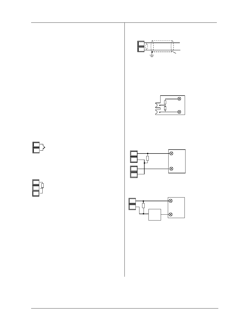
Linear Input (mA or mV)
•
If shielded cable is used it should be grounded in one
place only as shown
•
For a mA input
connect the 2.49Ω burden resistor
supplied between the V+ and V- terminals as shown
•
For a 0-10Vdc input an external input adapter is required
(not supplied).
Sensor break alarm does not operate with this adaptor
fitted.
2.4.4 Two-Wire Transmitter Inputs
100KΩ
806Ω
+
0-10V
Input
-
+
-
-
+
V+
V-
VI
V+
V-
-
2.49Ω
+
V+
V-
Shield
+
mA / mV input
-
Using internal 24V power supply (Series 3)
-
+
V+
V-
-
+
2-Wire
Transmitter
-
+
2.49Ω
3C
3D
Using external power supply
+
-
External power
supply
-
+
2-Wire
Transmitter
-
+
2.49Ω
V+
V-