4 front panel layout, 1 to set the target temperature, 2 alarms – Super Systems 3 Series User Manual
Page 18: 3 alarm indication, Front panel layout, To set the target temperature, Alarms, Alarm indication
Operations Manual
Series 3
18
4.4
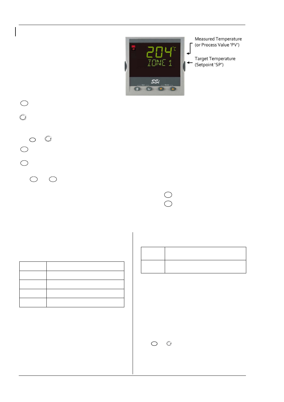
Front Panel Layout
ALM Alarm active (Red)
OP1 lit when output 1 is ON
OP2 lit when output 2 is ON
OP3 lit when output 3 is ON
OP4 lit when output 4 relay is ON
SPX Alternative setpoint in use (e.g. setpoint 2)
REM Remote digital setpoint. Also flashes when digital
communications active
MAN Manual mode selected
Operator Buttons:
Referred to as the ‘page’ button. From any view -
press to return to the HOME display
Referred to as the ‘scroll’ button. Press to select a new
parameter. If held down it will continuously scroll through
parameters.
Press
and
(ACK) together to acknowledge an alarm.
Referred to as the ‘arrow down’ button. Press to
decrease a value
Referred to as the ‘arrow up’ button. Press to increase
a value
Press
and
(MODE) together to toggle between Auto
and Manual mode.
4.4.1 To Set The Target Temperature.
From the HOME display:
Press
to raise the setpoint
Press
to lower the setpoint
The new setpoint is entered when the button is released
and is indicated by a brief flash of display.
4.4.2
Alarms
Process alarms may be configured using the Quick Start
Codes. Each alarm can be configured for:
Full Scale Low
The alarm is shown if the process value falls below a
set threshold
Full Scale High
The alarm is shown if the process value rises above a
set threshold
Deviation Low
The alarm is shown if the process value deviates below
the setpoint by a set threshold
Deviation High
The alarm is shown if the process value deviates above
the setpoint by a set threshold
Deviation Band
The alarm is shown if the process value deviates above
or
below the setpoint by a set threshold
If an alarm is not configured it is not shown in the list of
level 2 parameters.
Additional alarm messages may be shown such as
CONTROL LOOP BROKEN. This occurs if the controller
does not detect a change in process value following a
change in output demand after a suitable delay time.
Another alarm message may be INPUT SENSOR BROKEN
(SBr). This occurs if the sensor becomes open circuit; the
output level will adopt a ‘SAFE’ value which can be set up in
Operator Level 3..
From firmware version 2.11 two further alarm types
have been made available. These are:
Rising rate of
change
An alarm will be detected if the rate of change
(units/minute) in a positive direction exceeds the alarm
threshold
Falling rate of
change
An alarm will be detected if the rate of change
(units/minute) in a negative direction exceeds the alarm
threshold
These alarms cannot be configured by the Quick Start Code
– they can only be configured in Configuration Mode..
4.4.3
Alarm Indication
If an alarm occurs, the red ALM beacon will flash. A
scrolling text message will describe the source of the alarm.
Any output (usually a relay) attached to the alarm will
operate. An alarm relay can be configured using the Quick
Start Codes to be energised or de-energised in the alarm
condition. It is normal to configure the relay to be de-
energised in alarm so that an alarm is indicated if power to
the controller fails.
Press
and
(ACK) together to acknowledge an alarm.
If the alarm is still present the ALM beacon will light
continuously otherwise it will go off.
The action which takes place depends on the type of alarm
configured: