5 to calibrate remote setpoint input, To calibrate remote setpoint input, N o n e – Super Systems 3 Series User Manual
Page 88
Operations Manual
Series 3
88
14.3.5
To Calibrate Remote Setpoint Input
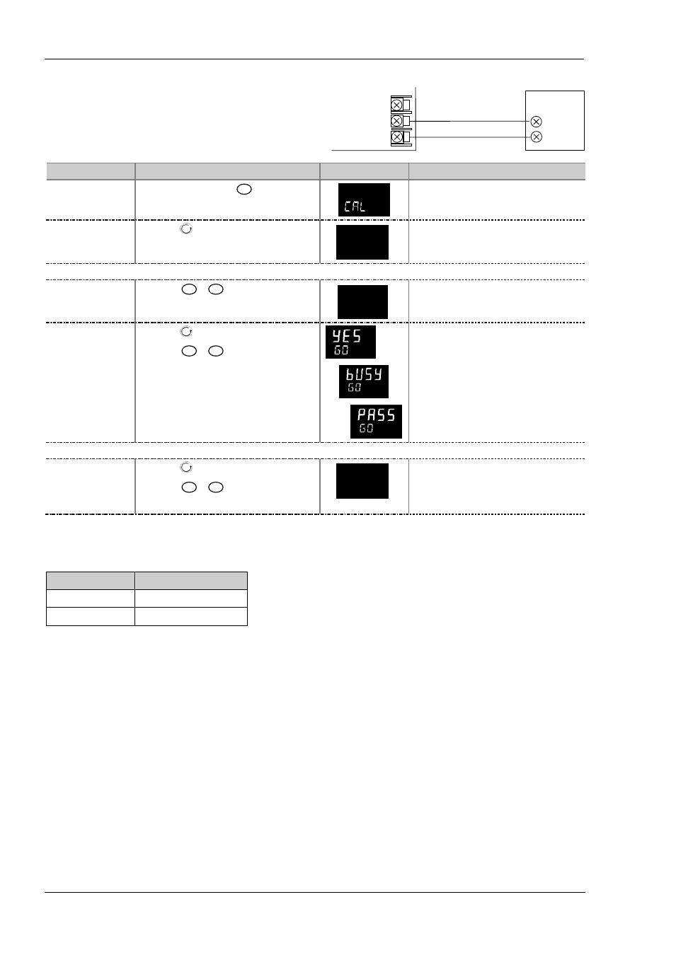
Connect a milli amp source to terminals HD and HE as shown.
Select Conf Level, then:
Operation
Do This
Display View
Additional Notes
Select the Calibration
List header
1.
From any display press
as many times as
necessary until the ‘CAL’ page header is displayed.
Scrolling display ‘
C A L I B R A T I O N L I S T
’
Select the Calibration
Phase
2.
Press
to select ‘P H A S E ’
n o n e
p h a s e
Scrolling display ‘
C A L I B R A T I O N p h a s e
’
Set mA source for 4mA
Select the low
calibration point
3.
Press
or
to choose ‘rm.CL’
r m.CL
p h a s e
Calibrate the
instrument to the low
calibration point (4mA)
4.
Press
to select ‘G O ’
5.
Press
or
to choose ‘YES’
Scrolling display ‘
C A L I B R A T I O N s t a r t
’
The controller automatically calibrates to the
injected input. The display will show
busy
then
pass
,
(if calibration is successful.) or ‘
FAIL
’
if not.
Fail may be due to incorrect input. mA
Set mV source for 20mA
Select the high
calibration point
9.
Press
to select ‘P H A S E ’
10. Press
or
to choose ‘rm.CH’
11. Repeat 4 and 5 above to calibrate the high point
r m.CH
p h a s e
The controller will again automatically calibrate to
the injected input mV.
If it is not successful then ‘
FAIL’
will be displayed
To calibrate the voltage input, connect a volts source to terminals HD (negative) and HF (positive). The procedure is the same as
described above but the calibration points are
Parameter
Calibration Voltage
rm.VL
0 Volts
rm.VH
10 Volts
Copper cable
Current
Source
-
+
Controller HD
HF
HE
-
+