Switch on, 1 new controller, 1 quick start code – Super Systems 3 Series User Manual
Page 16: New controller, Quick start code
Operations Manual
Series 3
16
4.
Switch On
The way in which the controller starts up depends on factors
described below in sections 4.1, 4.2 and 4.3.
4.1
New Controller
If the controller is new AND has not previously been
configured it will start up showing the ‘Quick Configuration’
codes. This is a built in tool which enables you to configure
the input type and range, the output functions and the
display format.
!
Incorrect configuration can result in damage to the
process and/or personal injury and must be carried out by a
competent person authorised to do so. It is the
responsibility of the person commissioning the controller to
ensure the configuration is correct
4.1.1
Quick Start Code
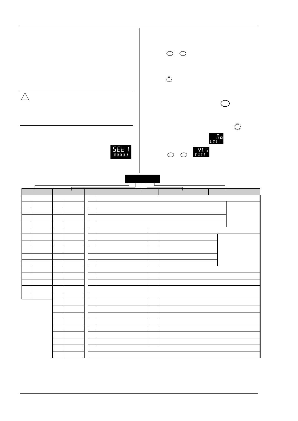
The quick start code consists of two ‘SETS’ of
five characters. The upper section of the
display shows the set selected, the lower
section shows the five digits which make up
the set.
Adjust these as follows:.
1. Press any button
.
The characters will change to ‘-‘, the
first one flashing.
2. Press
or
to change the flashing character to the
required code shown in the quick code tables – see
below. Note: An
x
indicates that the option is not
fitted.
3. Press
to scroll to the next character.
You cannot scroll to the next character until the current
character is configured.
To return to the first character press
4. When all five characters have been configured the
display will go to Set 2.
5. When the last digit has been entered press
again,
the display will show
6. Press
or
to
.
The controller will then automatically go to the operator
level.
SET 1
Input type
Range
Input/Output 1
Output 2
Output 4
Thermocouple
Full range
X
Unconfigured
B
Type B
C
o
C
H
PID Heating [logic, relay (1) or 4-20mA] or motor valve open [VC and VP only]
Note (1) O/P4 is relay
only.
J
Type J
F
o
F
C
PID Cooling [logic, relay (1) or 4-20mA] or motor valve close [VC and VP only]
K
Type K
Centigrade
J
ON/OFF Heating [logic or relay (1)], or PID 0-20mA heating
L
Type L
0
0-100
K
ON/OFF Cooling [logic or relay (1)], or PID 0-20mA cooling
N
Type N
1
0-200
Alarm
(2)
: energised in alarm
Alarm
(2)
: de-energised in alarm
R
Type R
2
0-400
0
High alarm
5
High alarm
Note (2)
OP1 = alarm 1
OP2 = alarm 2
OP3 = alarm 3
OP4 = alarm 4
S
Type S
3
0-600
1
Low alarm
6
Low alarm
T
Type T
4
0-800
2
Deviation high
7
Deviation high
C
Custom
5
0-1000
3
Deviation low
8
Deviation low
RTD
6
0-1200
4
Deviation band
9
Deviation band
P
Pt100
7
0-1400
DC Retransmission (not O/P4)
Linear
8
0-1600
D
4-20mA Setpoint
N
0-20mA Setpoint
M 0-80mV
9
0-1800
E
4-20mA Temperature
Y
0-20mA Temperature
2
0-20mA
Fahrenheit
F
4-20mA output
Z
0-20mA output
4
4-20mA
G
32-212
Logic input functions (Input/Output 1 only)
H
32-392
W Alarm acknowledge
V
Recipe 2/1 select
J
32-752
M Manual select
A
Remote UP button
K
32-1112
R
FEATURE UNAVAILABLE
B
Remote DOWN button
L
32-1472
L
Keylock
G
FEATURE UNAVAILABLE
M
32-1832
P
Setpoint 2 select
I
FEATURE UNAVAILABLE
N
32-2192
T
FEATURE UNAVAILABLE
Q
Standby select
P
32-2552
U
Remote SP enable
R
32-2912
T
32-3272
K C H C 0