2 remote digital setpoint select and remote fail, 3 sense, 4 source – Super Systems 3 Series User Manual
Page 38: 5 power fail, Remote digital setpoint select and remote fail, Sense, Source, Power fail, Rely 1.i d, D.out 1 . f u n c
Operations Manual
Series 3
38
9.1.2
Remote Digital Setpoint Select and
Remote Fail
These parameters were added in software version 1.11, and
subsequent versions, and are associated with the
retransmission of remote setpoint through master comms.
‘rmt’
allows the remote setpoint to be selected via a digital
input and ‘rmt.F’ is a flag which is set if no comms activity is
detected for 5 seconds or more when writing to the remote
setpoint. The flag is reset when writing to the remote
setpoint resumes.
9.1.3
Sense
If the module is an output, ‘normal’ means a relay output is
energised for 100% PID demand. For a heating or cooling
output, set this parameter to ‘nor’.
‘Inverted’ means a relay output is energised for 0% PID
demand
For an alarm output set this parameter to ‘Inv’ so that it de-
energises to the alarm state.
If the module is an input, ‘normal’ means the function is
activated when the input contact is closed, and ‘inverted’
means the function is activated when the input contact is
open.
9.1.4
Source
The four parameters SOURCE A, SOURCE B, SOURCE C,
and SOURCE D appear when the output is configured as a
digital output i.e. ‘-.FUNC’ = ‘d.Out’ and provide the facility
to connect up to four alarms or events to operate a single
output (normally configured as a relay). If any one of the
events becomes true then the output relay will operate.
9.1.5
Power Fail
An output, configured as a digital output, can be made to
operate following a power fail. It can be acknowledged in
the same manner as an alarm but no alarm message is given.
9.1.6
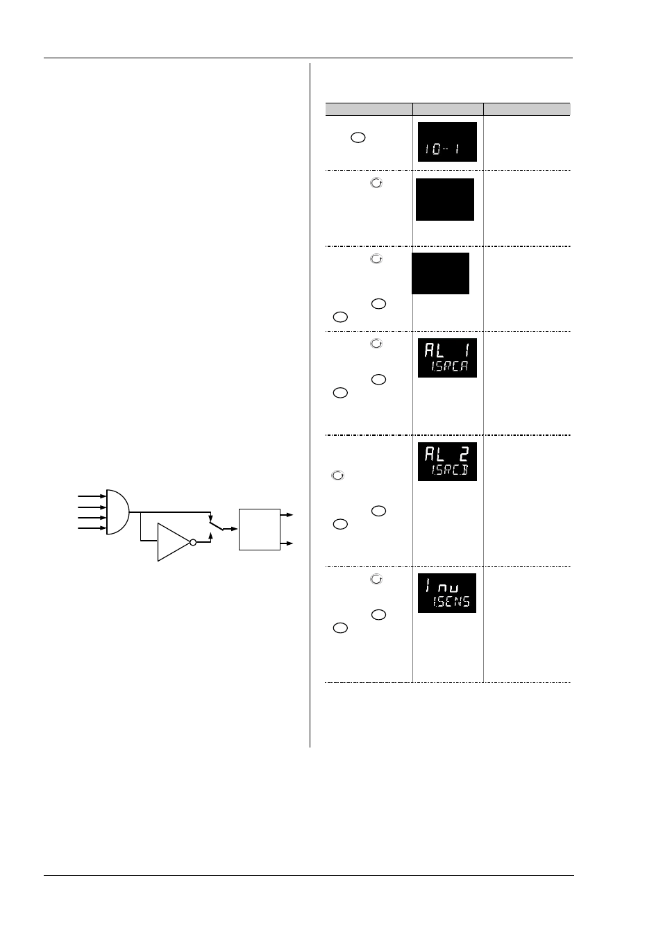
Example: To Configure IO-1 Relay to
Operate on Alarms 1 and 2:
Do This
Display
Additional Notes
1.
From any display,
press
as many
times as necessary to
select ‘I O -1’
Scrolling display ‘i o -
1 l i s t
’
2.
Press
to
scroll to ‘1. I D ’
This is the identification
of the hardware fitted
and cannot be adjusted.
3.
Press
to
scroll to
‘1. F U N C ’
4.
Press
or
to select ‘d.out’
The output is
configured as a digital
output function.
Scrolling display ‘i o
1 f u n c t i o n
’
5.
Press
to
scroll to ‘1. S R C . A ’
6.
Press
or
to select the
event which you want
to operate the output,
eg ‘AL.1’
The output will activate
if either alarm 1 or
alarm 2 occur .
Scrolling display ‘i o
1 s o u r c e a
’
7.
If a second event
is required to operate
the same output, press
to select
‘1. S R C . B ’
8.
Press
or
to select the
second event which you
want to operate the
output, eg ‘AL.2’
Scrolling display ‘i o
1 s o u r c e b
’
Continue to select up to
four events if required
using 1.S R C . C and
1 . S R C . D
9.
Press
to
scroll to ‘1. S E N S ’
10. Press
or
to select ‘Inv’
‘Inverted’ means a relay
output is energised for
0% PID demand
‘Normal’ means a relay
output is energised for
100% PID demand
Scrolling display ‘i o 1
s e n s e
’
OR
SEnS
Output
(relay)
Nor
Inv
SRC.A
SRC.B
SRC.C
SRC.D
reLy
1.i d
d.out
1 . f u n c