Digital communications, 1 digital communications wiring, 1 eia485 (2-wire) – Super Systems 3 Series User Manual
Page 69: Digital communications wiring, Eia485 (2-wire)
Series 3
Operations Manual
69
13. Digital Communications
Digital Communications (or ‘comms’ for short) allows the
controller to communicate with a PC or a networked
computer system.
This product conforms to MODBUS RTU protocol a full
description of which can be found on www.modbus.org.
Two ports are available both using MODBUS RTU
communication facilities:
1. a configuration port - intended to communicate with a
system to download the instrument parameters and to
perform manufacturing tests and calibration
2. an EIA485 port on terminals HD, HE and HF - intended
for field communications using, for example, a PC
running a SCADA package.
The two interfaces cannot operate at the same time.
Each parameter has its own unique Modbus address. A list
of these is given at the end of this section.
13.1
Digital Communications Wiring
13.1.1
EIA485 (2-wire)
To use EIA485, buffer the EIA232 port of the PC with a
suitable EIA232/EIA485 converter. The use of a EIA485
board built into the computer is not recommended since
this board may not be isolated, which may cause noise
problems, and the RX terminals may not be biased correctly
for this application.
To construct a cable for EIA485 operation use a screened
cable with one (EIA485) twisted pair plus a separate core for
common. Although common or screen connections are not
necessary, their use will significantly improve noise
immunity.
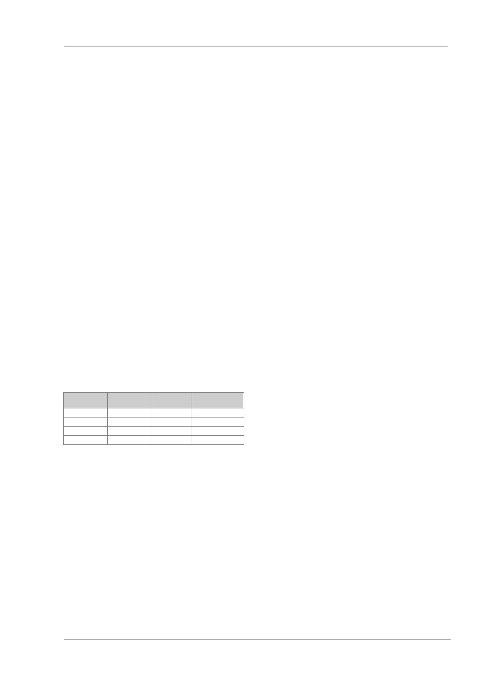
The terminals used for EIA485 digital communications are
listed in the table below.
Standard Cable
Colour
PC Function *
Instrument
Terminal
Instrument
Function
White
Receive, RX+
HF (B) or (B+)
Transmit, TX
Red
Transmit, TX+
HE (A) or (A+)
Receive, RX
Green
Common
HD
Common
Screen
Ground
•
These are the functions normally assigned to socket
pins. Please refer to your PC manual.