Controller block diagram, Inputs control processes outputs – Super Systems 3 Series User Manual
Page 31
Series 3
Operations Manual
31
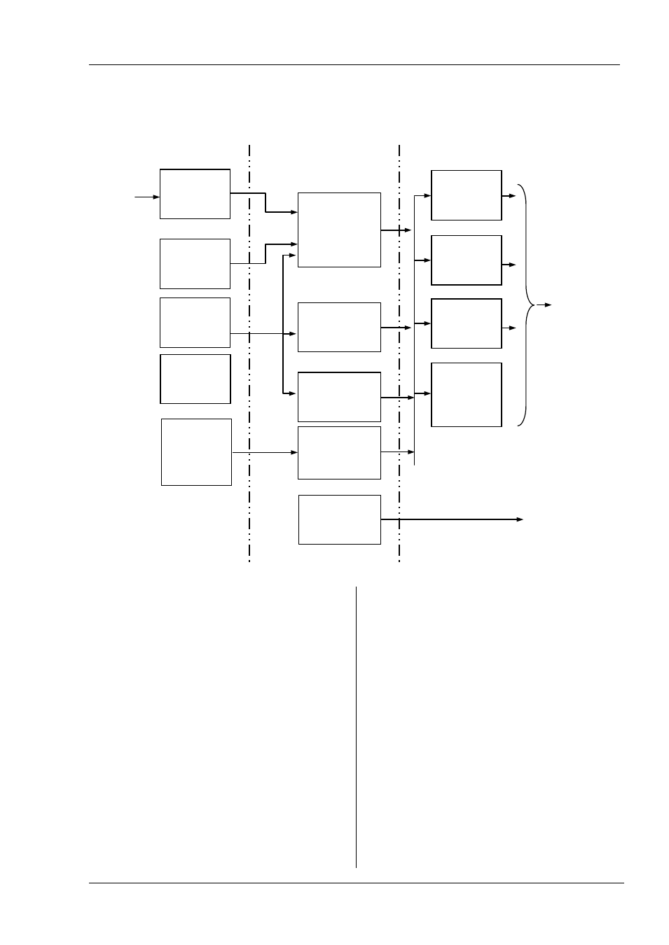
7. Controller Block Diagram
The block diagram shows the simple building blocks which make up the controller. Each block has a list of parameters headed by
a list name. For example the ‘Input List’ contains parameters which define the input type.
The quick start code automatically sets the parameters to match the hardware.
The Temperature (or Process Value, PV) is measured by the
sensor and compared with a Setpoint (SP) set by the user.
The purpose of the control block is to reduce the difference
between SP and PV (the error signal) to zero by providing a
compensating output to the plant via the output driver
blocks.
The timer blocks may be made to operate on a number of
parameters within the controller, and digital
communications provides an interface to data collection
and control.
The way in which each block performs is defined by its
internal parameters. Some of these parameters are
available to the user so that they can be adjusted to suit the
characteristics of the process which is to be controlled.
These parameters are found in lists and the name of each
list corresponds with the name of the function block shown
in the above diagram.
Sensor
eg thermocouple
Output 4 (AA
Relay)
Eg Alarm
AA
List
(section 9)
To plant
actuator
devices
Sensor Input
Input List
(section 8)
Setpoint
SP
List
(section 10)
Control
CTRL
List
PID/on-off/Tune/Auto-
Man
(section 11)
Input/Output 1
Eg Heat
I O-1
List
(section 9)
Output 2
Eg Cool
OP-2
List
(section 9)
Alarm(s)
ALARM
List
(section 12)
Timer
TI MER
List
(section 13)
Digital
Communications
COMMS
List
(section 15)
RS485
Digital Input A
LA
List
(section 9)
CT Alarm setting
CT
List
Not Supported
Current
Transformer
Input
CT
List
Not Supported
Inputs
Control
Processes
Outputs
Output 3
Eg Cool
OP-3
List
(section 9)
Digital Input B
LB
List
(section 9)