10.2 telnet/com1 configuration, Ioioi – RLE Falcon EM User Manual
Page 99
User Guide: Falcon FMS
Communication
www.rletech.com 970
484-6510
85
Pin 5 = Signal Ground
Pin 6 = No Connection
Pin 7 = Request to Send (internally connected to Pin 8)
Pin 8 = Clear to Send (internally connected to Pin 7)
Pin 9 = No Connection
( Female)
RS 232 Cable ( Straight Thru)
EXTERNAL DEVICE ( RTU - RS232 )
COM PORT
P 4 RJ11
TELCO
P 5 RJ45
NETWORK
IOIOI
P 3 RS232
COM2
IOIOI
P 2 RS232
COM1
SW1
+
-
GND
RS 485 COM1
IOIOI
COM1 SELECT
K 2
RX RX
485
K 1 TX TX
232
RELAY COM
2 COM1
485
T
E
R
M
SE
L
M
/S
TB 5 KEYPAD
TB4
NC NO C
RELAY
1
NC NO C
RELAY
2
1
2
ON
( Female)
( Male)
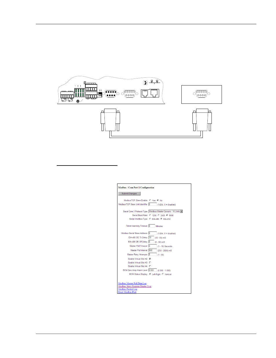
Figure 5-28: FMS connection to a EIA232 device.
5-10.2 Telnet/COM1 Configuration
The Com1 Port/Modbus/Telnet Configuration page allows the user to configure the FMS Telnet features.
Figure 5-29: Telnet/Com1Configuration Page
Serial Protocol: Configures the Serial COM Port 1 (EIA232 or EIA485) Master or Slave operation. The
options are:
None: Disables Modbus support on Serial Port COM1.