RLE Falcon EM User Manual
Page 84
Communication
User Guide: Falcon FMS
70 970
484-6510
www.rletech.com
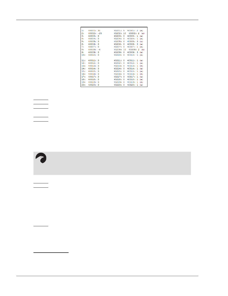
Figure 5-8: Modbus Slave Register Display Log
Column 1 = Displays the Falcon Channel or Input Number (1-104).
Column 2 = Displays the Falcon Slave Register Number for the Channel Input Reading.
Column 3 = Displays the Value of the Current Channel Input. Channels configured for digital will be a “0”
when the input is normal and “1” when the input is in alarm.
Column 4 = Displays the Falcon Slave Register Number for the Channel Input Alarm Status.
Column 5 = Displays the Contents of the Channel Input Alarm Register.
0 = No Alarm
1 = High 1 Alarm
2 = Low 1 Alarm
4 = High 2 Alarm
8 = Low 2 Alarm
10 = Digital Alarm
Column 6 = Displays the Falcon Slave Register Number for the Channel Input Configuration Status.
Column 7 = Displays the contents of the Channel Input Configuration Register.
0 = Not Installed.
1 = Not Configured
2 = Analog 4-20 mA
3 = Digital NO
4 = Digital NC
5 = Digital Status
6 = Analog 0-5VDC
7 = Analog 0-10VDC
Column 8 = Provides Additional Information for the Falcon Input.
(0) = Input is Not Installed (an Expansion Card not installed for this channel).
(a) = This Channel is an Analog Input (Main Board input or Expansion Card “A”).
(d) = This Channel is a Digital Input (Expansion Card “C”).
(R) = This Channel is a Relay Output.
5-3.3 Modbus Packet Log
This link displays a log of the Modbus packets that the FMS is sending and receiving.
NOTE:
The number displayed will be the sum of all active alarms. For example, if an input is
above the High1and High2 limits, the number displayed will be 5 (1 + 4 = 5).