Chapter 2: getting started, 1 installation, 2 falcon fms wiring – RLE Falcon EM User Manual
Page 18: Warning, 2.1 power supply and ground connections
Getting Started
User Guide: Falcon FMS
4 970
484-6510
www.rletech.com
CHAPTER 2: GETTING STARTED
In order to get the FMS working, users must install the unit, wire and connect the power, and set the IP
address. Any accessories for the FMS should also be connected at this time (e.g., keypad connection,
Modbus connections, Expansion Cards, etc.)
2-1
INSTALLATION
The Falcon FMS comes in a 19 inch (.48m) rack mount enclosure. Install the FMS in the rack. Use the
proper anchoring method to mount the unit securely. Supply either 24VDC (standard) or 48VDC (optional)
to the unit.
2-2
FALCON FMS WIRING
RLE Technologies recommends an 18AWG stranded copper wire for connection from each monitored
point to a terminal block (TB) connection on the FMS. RLE recommends no more than 500 feet (152.4m)
of wire at this specification. If longer runs are needed, please contact RLE Technologies for application
guidance. Shielded twisted pair wiring is recommended for analog signal transmitters being wired outside
of conduit runs and dropped ceiling applications.
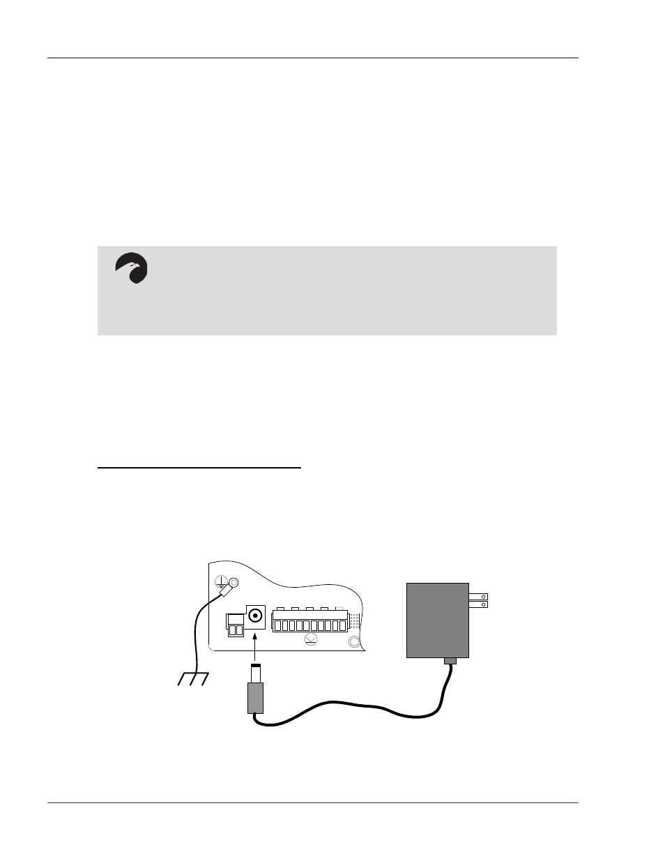
2-2.1 Power Supply and Ground Connections
Connect an 18AWG ground wire from the ground terminal to a suitable earth ground. For 24VDC model
FMS, plug the wall adapter into P1 and a UPS outlet as shown below. The wall adapter has a 5 foot
(1.524m) power cord. RLE Technologies recommends powering the FMS from a UPS supply to allow the
FMS to send alarm notification during a power outage.
P1
VDC
TB1
VDC
+ -
EXTERNAL
24VDC
+ +
Ch1
+ -
Ch2
+ -
Ch3
+ -
Ch4
+ -
TB2 Input 1-4
Figure 2-1: 24VDC Power Supply Connection
WARNING!!
Units have different model numbers. Before applying power to the unit, verify the
model number and power rating located on the back of the unit. The voltage
indicator is the last number on the unit model number. The FMS will either be a
24VDC or a 48VDC.