RLE Falcon EM User Manual
Page 42
FMS Configuration
User Guide: Falcon FMS
28 970
484-6510
www.rletech.com
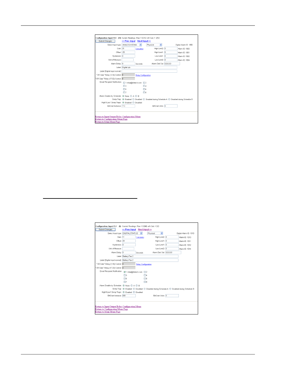
Figure 3-8: Expansion Card “A” Input Card
This page will be displayed when configuring an input on an Expansion Card “A”. It is identical to the
FMS Main Board Input Configuration page—see section 3-3.1, Main Board Input Configuration (Channels
1-8), pg. 23—with the following exceptions:
The Expansion Card “A” does not except common ground digital inputs. Therefore, the option for
Individual Ground Type (digital in only) is removed.
Analog 0-5VDC and Analog 0-10VDC options are added to the Input Type. The Expansion Card
“A” accepts analog inputs individually configurable through internal jumpers, as 4-20mA, 0-
5VDC or 0-10VDC.
3-3.3 Expansion Card “C” Input Configuration
To configure Expansion Card C, select the desired input or relay from the Input and Relay Configuration
page; see Figure 3-4, pg. 22. While units will vary depending on individual configurations, Expansion Card
C is typically numbered 1.1–1.24, 2.1–2.24, etc.
Figure 3-9: Sample of Falcon FMS Configuration Main Menu