Figure 2-5: relay output wiring examples, 120vac l n, 24vdc comm – RLE Falcon EM User Manual
Page 23
User Guide: Falcon FMS
Getting Started
www.rletech.com 970
484-6510
9
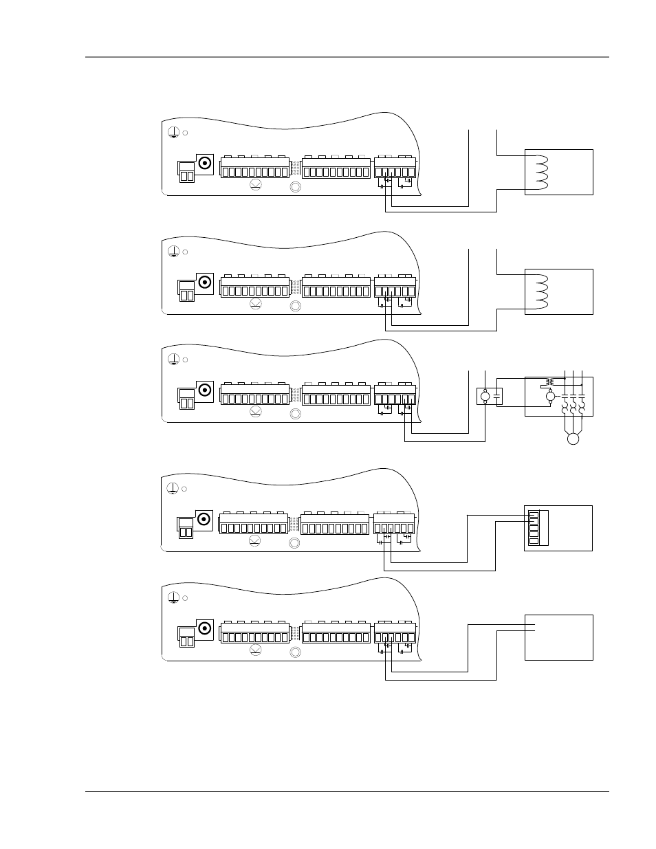
FMS for Normally Open (NO—unsupervised or normally de-energized), or Normally Closed (NC—
supervised or normally energized) operation; see Figure 2-5: Relay Output Wiring Examples for examples.
P1
VDC
TB1
VDC
+ -
EXTERNA
L
24VDC
+ +
Ch1
+ -
Ch2
+ -
Ch3
+ -
Ch4
+ -
TB2 Input 1-
4
Ch5
+ -
Ch6
+ -
Ch7
+ -
TB3 Input 5-
8
Ch8
+ -
EXTERNA
L
GND
- -
TB4
NC NO
C
RELAY
1
NC NO
C
RELAY
2
Motor
Starter
Blower
Motor
Interposing
Relay
Control Power for
Interposing Relay
NOTES:
1. Interposing Relay may not be required if Motor Starter control power is
120VAC and requires less than 0.5A.
2. Control Power for interposing relay can be connected to the Motor
Starter if the Motor Starter control power is 120VAC
P1
VDC
TB1
VDC
+ -
EXTERNA
L
24VDC
+ +
Ch1
+ -
Ch2
+ -
Ch3
+ -
Ch4
+ -
TB2 Input 1-
4
Ch5
+ -
Ch6
+ -
Ch7
+ -
TB3 Input 5-
8
Ch8
+ -
EXTERNA
L
GND
- -
TB4
NC NO
C
RELAY
1
NC NO
C
RELAY
2
120VAC Door
Unlatch Solenoid
120VAC
L N
P1
VDC
TB1
VDC
+ -
EXTERNA
L
24VDC
+ +
Ch1
+ -
Ch2
+ -
Ch3
+ -
Ch4
+ -
TB2 Input 1-
4
Ch5
+ -
Ch6
+ -
Ch7
+ -
TB3 Input 5-
8
Ch8
+ -
EXTERNA
L
GND
- -
TB4
NC NO
C
RELAY
1
NC NO
C
RELAY
2
24Vdc Door Unlatch
Solenoid
+24VDC Comm.
P1
VDC
TB1
VDC
+ -
EXTERNA
L
24VDC
+ +
Ch1
+ -
Ch2
+ -
Ch3
+ -
Ch4
+ -
TB2 Input 1-
4
Ch5
+ -
Ch6
+ -
Ch7
+ -
TB3 Input 5-
8
Ch8
+ -
EXTERNA
L
GND
- -
TB4
NC NO
C
RELAY
1
NC NO
C
RELAY
2
Web Camera
External
Sensor
Input
P1
VDC
TB1
VDC
+ -
EXTERNA
L
24VDC
+ +
Ch1
+ -
Ch2
+ -
Ch3
+ -
Ch4
+ -
TB2 Input 1-
4
Ch5
+ -
Ch6
+ -
Ch7
+ -
TB3 Input 5-
8
Ch8
+ -
EXTERNA
L
GND
- -
TB4
NC NO
C
RELAY
1
NC NO
C
RELAY
2
RA1X2
RASP1
Provides
Audible
Alarm
Figure 2-5: Relay Output Wiring Examples