RLE Falcon EM User Manual
Page 85
User Guide: Falcon FMS
Communication
www.rletech.com 970
484-6510
71
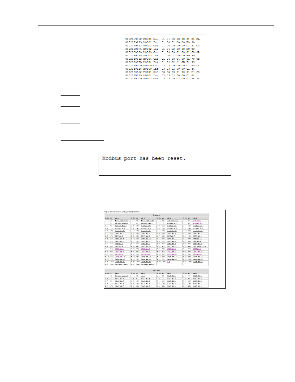
Figure 5-9: Modbus Packet Log
Column 1 = System Up Time.
Column 2 = Modbus Master Register Number.
Column 3 = Direction of Packet:
OUT = Packet Sent from the Falcon (Master Request).
IN = Packet Received by the Falcon (Slave Response).
Column 4 = Modbus Packet.
5-3.4 Reset Modbus Port
This link allows users to reset the Modbus port so that the contents of the polling registers will be cleared.
Figure 5-10: Modbus Rest Port Confirmation
5-4
CONFIGURING INPUTS AND RELAYS FOR SLAVE UNITS (MODBUS &
BACNET)
Select any input not currently in use.
Figure 5-11: Input and Relay Configuration Menu
This page allows users to configure the input features.