RLE Falcon EM User Manual
Page 115
User Guide: Falcon FMS
FMS Expansion Cards
www.rletech.com 970
484-6510
101
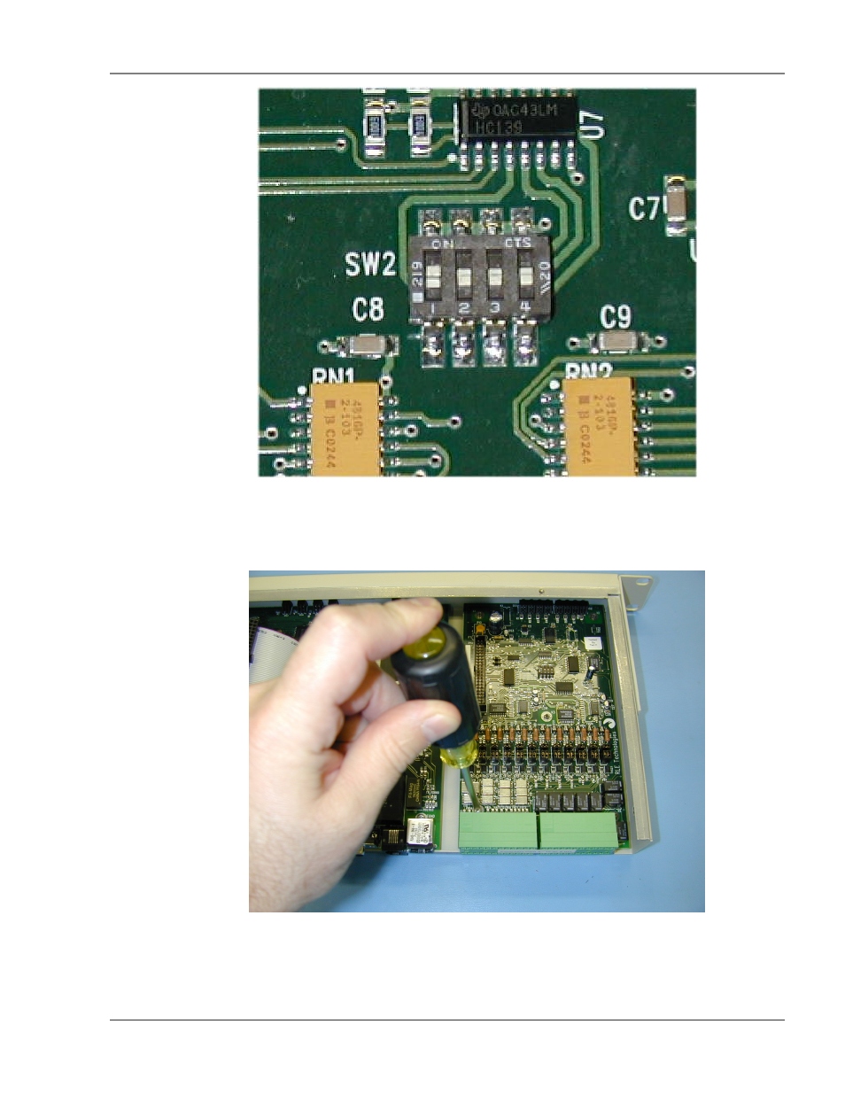
Figure A-1: Expansion Card SW2 Dip Switch
5. Align the holes in the card with the four posts and one screw setting on the main FMS unit. Make
sure the two double rows of pins align next to each other, and the green inputs point toward the rear
of the unit.
Figure A-2: Expansion Card Mounting in a One Rack Unit
See also other documents in the category RLE Equipment:
- LD2000 Quick Start (2 pages)
- LD300 (2 pages)
- LDZ4 (19 pages)
- LD2000 (78 pages)
- LD5100 Quick Start (2 pages)
- LD310 (2 pages)
- LD5000 Quick Start (4 pages)
- LD1000 (2 pages)
- LD5100 (72 pages)
- 10K Quick Start (2 pages)
- F200 (2 pages)
- LDRA6 Quick Start (2 pages)
- 10K V.2.5.a (44 pages)
- LD1500 Quick Start (2 pages)
- LD5000 (92 pages)
- LD2100 Quick Start (2 pages)
- LD5200 Quick Start (2 pages)
- LD1500 V.3.1 (52 pages)
- FDS-Wi Quick Start (2 pages)
- GD100 (26 pages)
- FDS-Wi V.2.5 (74 pages)
- LD2100 V.2.6 (92 pages)
- LD5200 V.2.3 (118 pages)
- F-Series Quick Start (2 pages)
- F110 Quick Start (2 pages)
- Wi-MGR Quick Start (2 pages)
- Wi-MGR V.1.6 (74 pages)
- FMS Quick Start (2 pages)
- FMS32 (92 pages)
- Ground Fault Monitor (2 pages)
- RA1x2 (2 pages)
- Protocol Converter Quick Start (2 pages)
- Protocol Converter V.2.4 (70 pages)
- FMS V.1.13 (226 pages)