2.10 expansion card a connections, Ioioi – RLE Falcon EM User Manual
Page 27
User Guide: Falcon FMS
Getting Started
www.rletech.com 970
484-6510
13
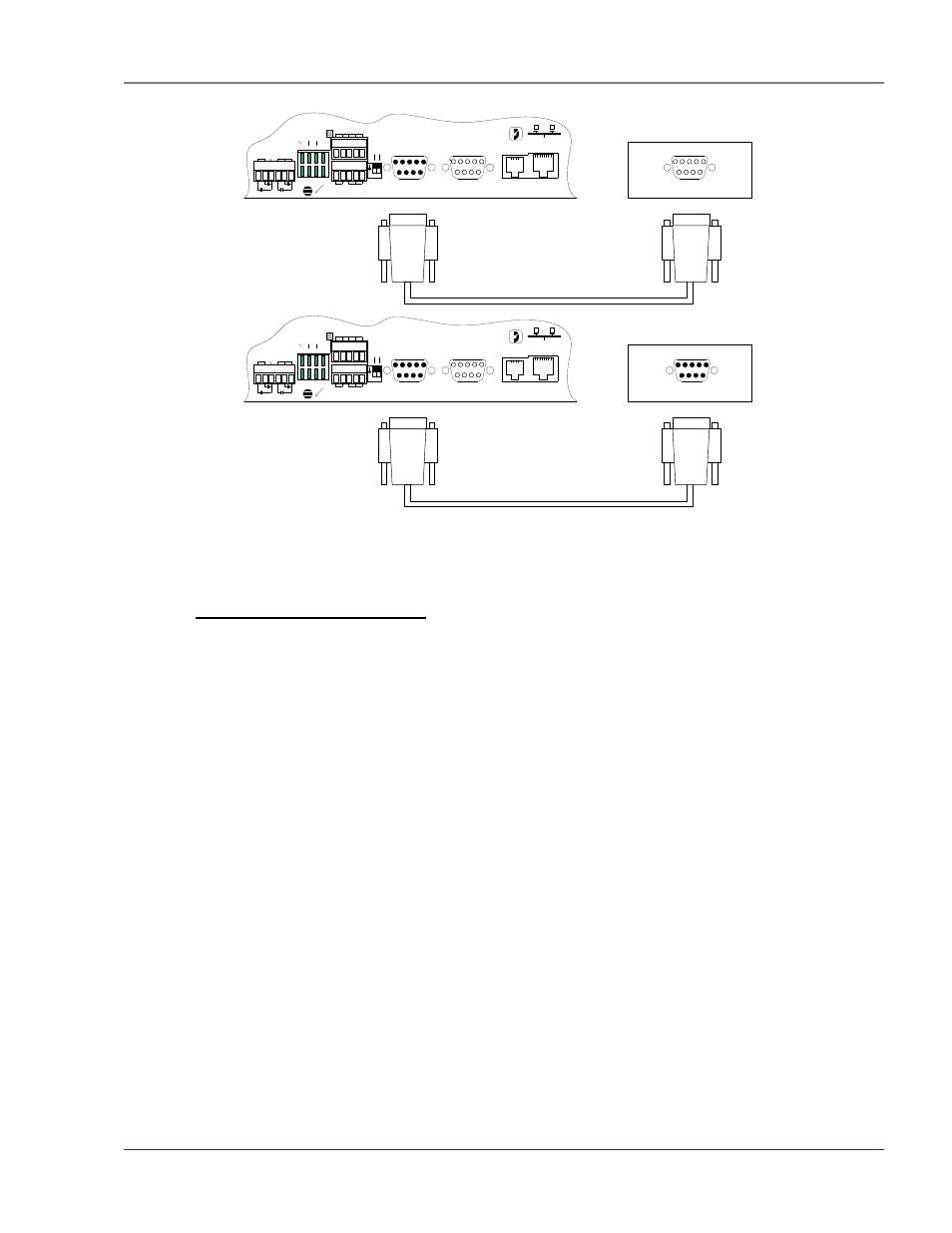
(Female)
RS232 Cable (Straight Thru)
MODBUS DEVICE (RTU - RS232/DCE)
COM PORT
P4 RJ11
TELCO
P5 RJ45
NETWORK
IOIOI
P3 RS232
COM2
IOIOI
P2 RS232
COM1
SW1
+ - GND
RS485 COM1
IOIOI
COM1 SELECT
K2 RX RX 485
K1 TX TX 232
RELAY COM2 COM1
48
5 T
E
R
M
SE
L
M
/S
TB5 KEYPAD
TB4
NC NO C
RELAY 1
NC NO C
RELAY 2
1 2
ON
(Female)
(Male)
(Female)
RS232 Cable (Null Modem)
MODBUS DEVICE (RTU - RS232/DTE)
COM PORT
P4 RJ11
TELCO
P5 RJ45
NETWORK
IOIOI
P3 RS232
COM2
IOIOI
P2 RS232
COM1
SW1
+ - GND
RS485 COM1
IOIOI
COM1 SELECT
K2 RX RX 485
K1 TX TX 232
RELAY COM2 COM1
485 TE
R
M
SE
L M
/S
TB5 KEYPAD
TB4
NC NO C
RELAY 1
NC NO C
RELAY 2
1 2
ON
(Female)
(Male)
Figure 2-11: FMS EIA232 Connection to a DCE or DTE Device
2-2.10 Expansion Card A Connections
A sticker identifying the Expansion Cards as A or C is located on each Expansion Card. The following
wiring diagrams show the Expansion Card in Slot 1. However, the Expansion Card may be in Slot 2, 3 or 4
based on the FMS configuration. The I/O for each card type appears on the back of the FMS for reference
during field wiring; see Figure 2-13 pg. 14 and Figure 2-16, pg. 16 for typical wiring. For information on
Expansion Card B, see APPENDIX H: Expansion Card B, pg. 127.
Expansion Card A has 12 non-isolated analog input channels and 8 relay output channels. The analog input
channels can be wired for 4-20mA, 0-5VDC, 0-10VDC, NO (normally open) dry contact or NC (normally
closed) dry contact. The circuit board has internal jumpers to select an mA input or a voltage input. The
factory default is set as a 4-20mA input. See APPENDIX A: FMS Expansion Cards, pg. 100, for jumper
location and settings.