Ioioi – RLE Falcon EM User Manual
Page 79
User Guide: Falcon FMS
Communication
www.rletech.com 970
484-6510
65
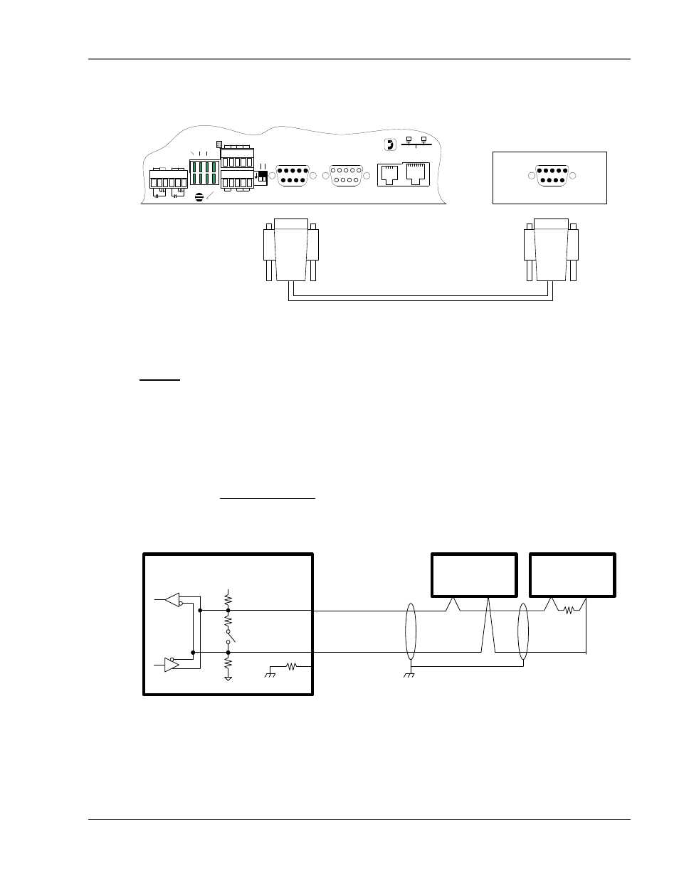
Figure 5-1: FMS Modbus EIA232 Connection to an EIA232 DCE Device
(Female)
RS232 Cable (Null Modem)
MODBUS DEVICE (RTU - RS232/DTE)
COM PORT
P4 RJ11
TELCO
P5 RJ45
NETWORK
IOIOI
P3 RS232
COM2
IOIOI
P2 RS232
COM1
SW1
+ - GND
RS485 COM1
IOIOI
COM1 SELECT
K2 RX RX 485
K1 TX TX 232
RELAY COM2 COM1
485 TE
R
M
SEL
M
/S
TB5 KEYPAD
TB4
NC NO C
RELAY 1
NC NO C
RELAY 2
1 2
ON
(Female)
(Male)
Figure 5-2: FMS Modbus EIA232 Connection to an EIA232 DTE Device
5-2.2 EIA485
The EIA485 COM Port 1 on the FMS is used to connect the FMS—as a Modbus Master—to one or more
Modbus Slave devices or it is used to connect a Modbus Master device to the FMS as a Modbus Slave.
The Modbus EIA485 is active over COM1 (TB5 Pins 8, 9 and 10). The EIA485 port allows
communications between one Modbus Master and one or more Modbus Slave devices. EIA485 can
accommodate up to 4,000 feet (1,219m) of cable length. There are many variations on how terminals are
labeled on EIA485 2-wire (e.g., some devices use (+) and (-) or A and B, and some use (–) and (+) or B and
A. Therefore, if a Slave unit is not responding, try swapping the wires.
COM1 TB5 Pin Out
Pin 8 = EIA485(+)
Pin 9 = EIA485(-)
Pin 10 = Ground
FALCON COM1 RS485 -
TB5 Pins 8-10
+5V
20K
100 (Termination)
20K
Sw1-1
(down = closed)
8 (RS485 +)
9 (RS485 -)
100
10 (RS485 GND)
R
D
B
A
Remote Device
RS485, 2-Wire
B
A
Remote Device
RS485, 2-Wire
100
(Termination)
Figure 5-3: EIA485 Wiring Connections