Digital i/o connections, Bit mode – Measurement Computing WaveBook rev.5.3 User Manual
Page 83
Digital I/O Connections
16-Bit Mode
For 16-bit mode, the following signals are present on the WaveBook’s DB25F high-speed digital I/O
connector. Note that 8-bit mode is covered in the following section.
16 High-Speed Digital I/O Lines (D0 through D15)
TTL Trigger Input (TTLTRG)
+15 V (pin 23), -15 V (pin 22), 50 mA max. (each)
two +5 V (pin 19 and pin 21), 250 mA max. (total)
External Clock Input (pin 20)
Digital Clock (pin 18), only used for WBK17 applications
two Digital Grounds (pins 24 and 25)
To sample just 16 digital input signals, connect them directly to the digital I/O data lines.
D15 is the most significant bit, and D0 is the least.
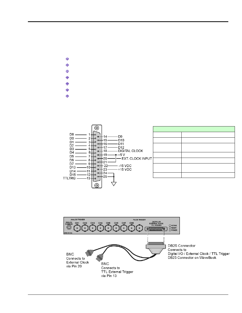
Digital I/O Connections, 16-Bit Mode
D0 through D15
High Speed Digital I/O data lines
TTLTRG
TTL trigger input
External Clock
Input
16 bit mode, read/write strobe,
Pin 20
+5 VDC
250 mA maximum
+15,-15 VDC
50 mA maximum (each)
Digital Clock
Pin 18, only used for WBK17
applications
Digital Grounds
Pins 24 and25
DB25 Pinout, 16-Bit Mode
The following figure depicts the WaveBook’s Front Panel. The DB25 connector and cable for External
Clock and TTL External Trigger are represented.
WaveBook with Optional Clock and External Trigger Cable (CA-178)
WaveBook/512A, /516, /516A , /516E
897895
WaveBook Operation Reference 4-13