Multiple wavebook systems, 2 examples – Measurement Computing WaveBook rev.5.3 User Manual
Page 67
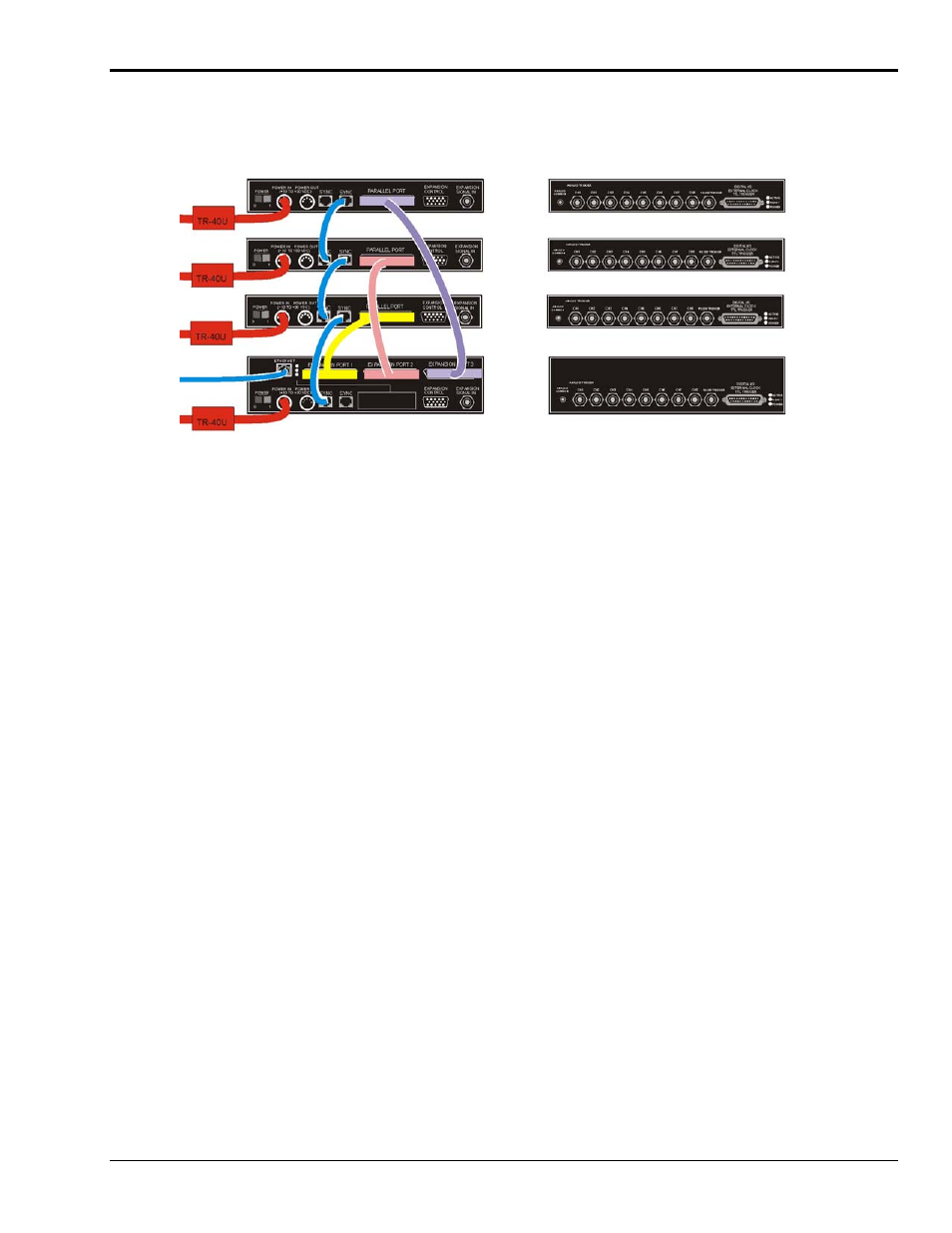
Multiple WaveBook Systems, 2 Examples
Example 1: A WaveBook/516E with 3 WaveBook/516A Units
Device Interface Side Channel Input Side
A WaveBook/516E with 3 WaveBook/516A Units
WaveBook/516A
(3
rd
)
WaveBook/516A
(2
nd
)
WaveBook/516A
(1
st
)
WaveBook/516E
Power
Power
Power
Ethernet
Power
Lines and Cables Used in Example 5, excluding channel input connections.
1. Power Supply - To the WaveBook/516E POWER IN DIN 5 connector, +10 VDC to +30 VDC,
typically from a TR-40U power adapter.
2. Power Supply – To each WaveBook/516A’s POWER IN DIN 5 connector, +10 VDC to +30 VDC.
Each unit uses its own dedicated TR-40U power adapter.
3. Ethernet – From the WaveBook/516E’s ETHERNET jack to a 10/100BaseT Ethernet Network or to
the ETHERNET jack on a PC. Applicable Ethernet patch cables (1.5-foot or 7-foot) are CA-242 and
CA-242-7, respectively.
4. Synchronization – From a WaveBook/516E SYNC jack to a SYNC jack on the first
WaveBook/516A. The connection is made via a CA-74-1 cable.
5. Synchronization – From the first WaveBook/516A’s remaining SYNC jack to a SYNC jack on the
second WaveBook/516A. The connection is made via a CA-74-1 cable.
6. Syncronization – From the second WaveBook/516A’s remaining SYNC jack to a SYNC jack on the
third WaveBook/516A. The connection is made via a CA-74-1 cable.
7. Expansion 1 – From the WaveBook/516E’s EXPANSION PORT 1 to the first WaveBook/516A’s
PARALLEL PORT connector. The connection is made via a 25-pin CA-35-12 cable.
8. Expansion 2 – From the WaveBook/516E’s EXPANSION PORT 2 to the second
WaveBook/516A’s PARALLEL PORT connector. The connection is made via a 25-pin CA-35-12
cable.
9. Expansion 3 – From the WaveBook/516E’s EXPANSION PORT 3 to the third WaveBook/516A’s
PARALLEL PORT connector. The connection is made via a 25-pin CA-35-12 cable.
WaveBook User’s Manual
897895
System Examples 3-7