Trigger input (ttl compatible), Signal out (conditioned analog outputs), Source output (excitation source) – Measurement Computing ZonicBook 618E rev.3.4 User Manual
Page 98: External clock
Specifications are subject to change without notice.
13-2 Specifications
918895
ZonicBook/618E
Trigger Input (TTL Compatible)
Connector: BNC
Input Signal Range: 0 to 5V, TTL compatible
Input Characteristics: TTL-compatible with 10k ohm pull-up resistor
Input Protection: Zener clamped, 0.7 to +5V
Latency: 300 ns
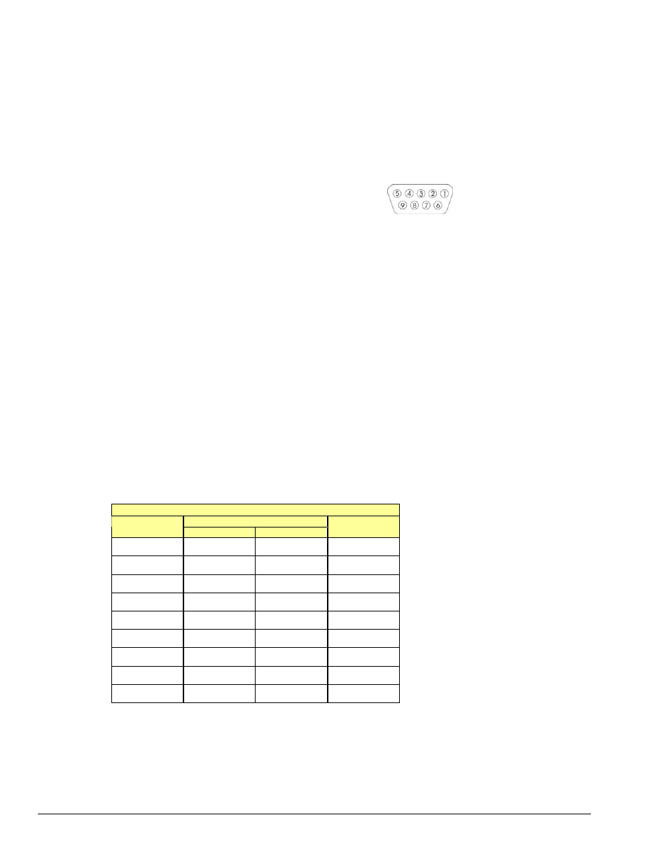
Signal Out (Conditioned Analog Outputs)
Each analog input signal is provided as a conditioned
analog output on the rear panel.
Channels: 8
Pin 1 = CH 2
Pin 6 = CH 1
Signal Connection: Female DB9
Pin 2 = CH 4
Pin 7 = CH 3
Amplitude: 0 to ±5 V max
Pin 3 = CH 6
Pin 8 = CH 5
Output Impedance: 50
Ω
Pin 4 = CH 8
Protection: 26 V transient voltage suppressor
Pin 5 = Signal Ground
Source Output (Excitation Source)
Channels: 1
Signal Connection: BNC
Frequency Range: 1 Hz to 5 kHz
Frequency Resolution: 0.01 Hz
Amplitude Settings (p-p): 10V, 5V, 2V, 1V, 500mV, 200mV, 100mV, 0mV
Waveform Modes: Continuous sine, Sweep sine
Output Impedance: 50
Ω
Accuracy:
±0.1dB
DC Accuracy, Excluding Noise
Applies to 2-Pole and Bypass Filter Modes
Accuracy at 0° to 50°C (32° to 122°F)
± % of Reading
Range
Typical
Maximum
Offset
±25V
0.5 1
±15mV
±5V
0.15 0.3 ±3mV
±2.5V
0.15 0.3 ±2mV
±1V
0.15 0.3 ±1mV
±500mV
0.15 0.3 ±1mV
±250mV
0.15 0.3 ±1mV
±100mV
0.15 0.4 ±1mV
±50mV
0.15 0.4 ±1mV
±25mV
0.2 0.4
±1mV
These numbers are valid for 1 year after calibration and over the
entire operating temperature range of the unit.
External Clock
BNC connector r
eserved for future use.