3 - connectors, indicators, and cables 3, Front panel connectors and indicators, Connectors, indicators, and cables 3 – Measurement Computing ZonicBook 618E rev.3.4 User Manual
Page 19
Connectors, Indicators, and Cables
3
Front Panel Connectors and Indicators …… 3-1
Rear Pannel Connectors, Indicators, and Power Switch …… 3-3
Associated Cables …… 3-5
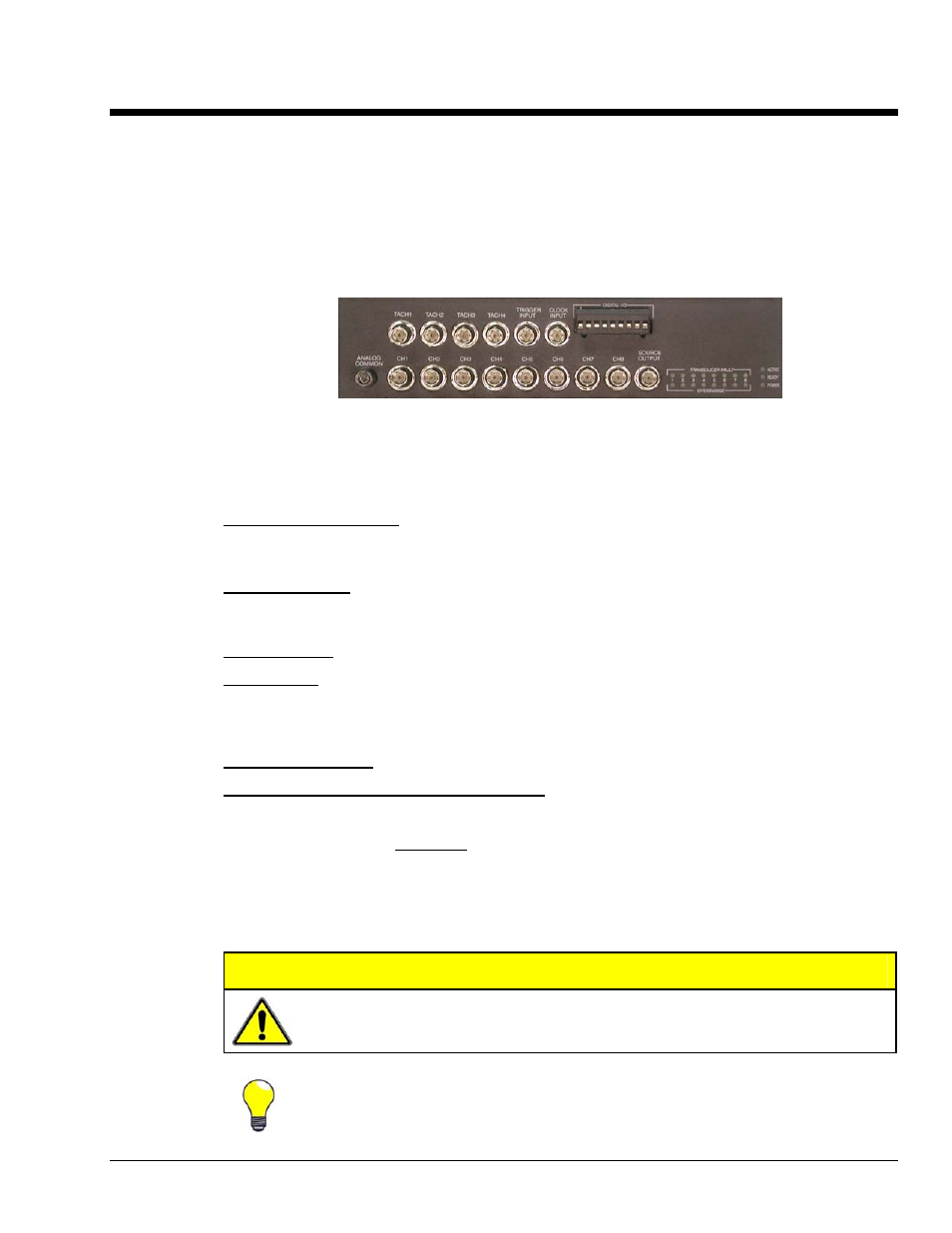
Front Panel Connectors and Indicators
ZonicBook/618E Front Panel
The ZonicBook/618E Front Panel includes the following connectors and LED indicators. The items are
listed from left to right, with the upper row presented first.
TACH 1 through TACH 4: These four BNC connectors are reserved for signal input from tachometers.
Tachometer signals going through these BNCs can be accepted through one of three modes: Counter,
Period, or Voltage.
TRIGGER INPUT: The Trigger Input BNC connector accepts a 0 to 5 volt TTL compatible signal as a
trigger source. Refer to your software documentation in regard to applicability and how to select the TTL
trigger input.
CLOCK INPUT: Reserved for future use.
DIGITAL I/O: The ZonicBook/618E includes a snap-in screw terminal block for easy connection of up to
8 Digital I/O lines. The connections are all designated as digital input or as digital output via software. To
make use of the Digital I/O feature, eZ-TOMAS or eZ-NDT must be used. Refer to the applicable
software document for details.
ANALOG COMMON: Common analog ground.
ANALOG SIGNAL INPUT CH 1 through CH 8: These eight BNC connectors are used for voltage
input. All input connections are made into the front panel BNCs, in which the BNC center conductor is the
signal HI and the BNC shell is the signal LO. The BNC shell is common among all eight input channels
(CH1 through CH8) and is not isolated from earth ground. Consequently, the shell is not meant to be
driven with respect to earth ground. An additional consideration exists regarding the setup of the input
transducer. If the transducer case is effectively earth grounded through its connection to a device under
test, there exists the possibility for added measurement noise due to the ground loop that is created. This
issue is minimized by electrically isolating the transducer from the test device. Note that a tachometer can
be connected to an analog input channel; however, that tachometer will be restricted to Voltage Mode.
CAUTION
The BNC shell is not to be driven with respect to earth ground. Attempting to do so
could result in equipment damage.
Additional measurement noise may be present when using earth grounded transducers.
For best results, electrically isolate the input transducers from earth ground.
ZonicBook/618E User’s Manual
918995
Connectors, Indicators, and Cables 3-1