Measurement Computing ZonicBook 618E rev.3.4 User Manual
Page 50
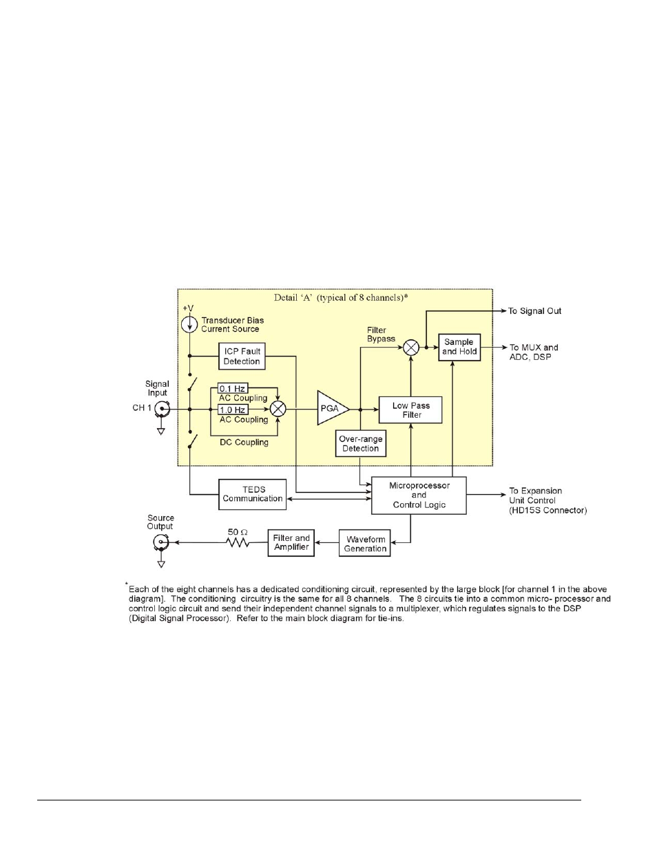
Features the dynamic signal conditioning circuit:
4 mA current source for transducer biasing
•
•
•
•
•
•
•
•
Hardware detection of a transducer fault
AC Coupling (0.1 Hz or 1 Hz high pass filter) or DC coupling (bypasses the filters)
Programmable gain amplifier (range selection)
Hardware overrange detection
Anti-aliasing low-pass filter
Simultaneous sample-and-hold (SSH) amplifier
Support for optional TEDS (Transducer Electronic Data Sheet), purchased option
All of these parameters are independently controlled in software on a per channel basis.
Note: The functionality of ZonicBook/618E’s dynamic signal conditioning circuitry is also found in the
WBK18 expansion module. Up to six WBK18 modules can be added to a ZonicBook/618E for
channel expansion.
The conditioning circuit includes a built-in programmable voltage excitation source. This source can be
used to stimulate dynamic systems for transfer function measurements, and also serves as a test signal for
the input channels.
Dynamic Signal Conditioning
Refer to Chapter 2 for the Complete ZonicBook/618E Block Diagram
6-2 Analog Signals
878595
ZonicBook/618E