Hardware setup – Measurement Computing ZonicBook 618E rev.3.4 User Manual
Page 114
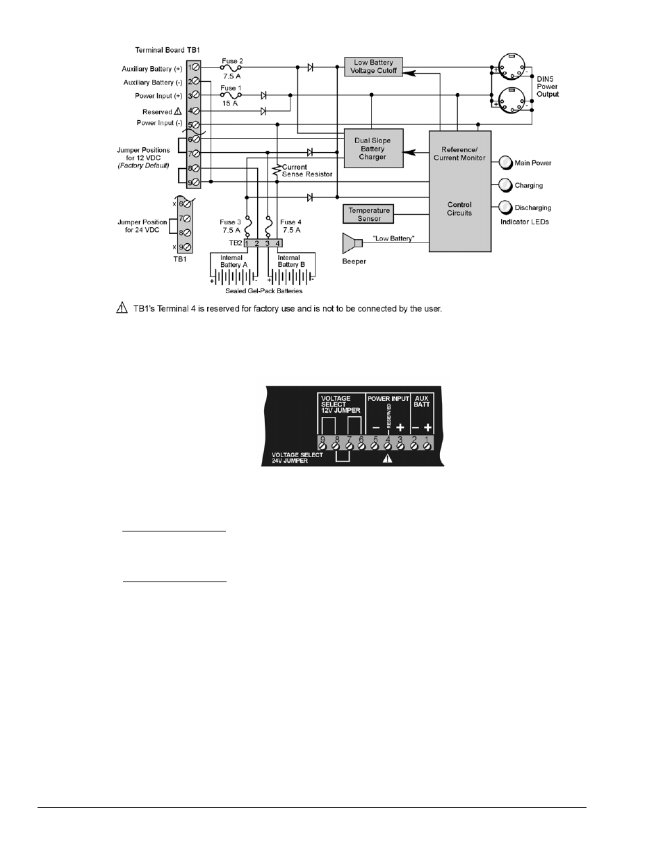
DBK34A Block Diagram
Hardware Setup
Configuration for 12 Volt (Default) or 24 Volt Operation
DBK34A’s Screw Terminal Board, TB1
DBK34A’s screw terminal numbers read from right to left (9,8,7…3,2,1) when viewed from the front
panel (see figure).
For 12 Volt Operation:
1. Remove jumper from terminals 8 and 7, if present.
2. Use a jumper to short terminals 9 and 8
3. Use a jumper to short terminals 7 and 6
For 24 Volt Operation:
1. Remove jumpers from terminals 9 and 8, if present
2. Remove jumpers from terminals 7 and 6, if present.
3. Use a jumper to short terminals 8 and 7.
Power
Power In (12 or 24 VDC only).
• Connect MAIN POWER INPUT (+) positive to Terminal 3 of TB1.
• Connect MAIN POWER INPUT (-) negative to Terminal 5 of TB1.
• TB1’s Terminal 4 is reserved for factory use and is not to be connected by the user.
• The use of an optional auxiliary battery will extend run-time. For use with DBK34A,
auxiliary batteries must be of lead-acid chemistry, in the 2 to 3 A-Hr range, and of the
same voltage as that set by the Voltage Select Jumpers. Auxiliary batteries charge and
discharge in the same manner as the internal batteries. If an auxiliary battery is to be used,
connect AUX BATT (+) positive to Terminal 1 (of TB1), and connect AUX BATT (-)
negative to Terminal 2 (of TB1).
C-6 Power Options
977995
ZonicBook/618E User’s Manual