Electrical grounding, Cable driving, Fk c v icc ib = − ⎛ ⎝ ⎜ ⎞ ⎠ ⎟ 2 – Measurement Computing ZonicBook 618E rev.3.4 User Manual
Page 63
Overload Recovery
Recovery time from clipping due to over-ranging is typically less than 1 ms. Recoveries from quasi-static
overloads that generate high DC bias shifts are controlled by the accelerometer input RC time constant that
is fixed during manufacture.
Connector
This parameter specifies the connector type and size (4-48, 6-40, 10-32 coaxial etc.) and the location on the
sensor, that is, top or side (usually on the hex base). Where there is no connector on the sensor, an integral
cable is specified with the length and the connector, that is, integral 6-ft to 10-32.
Electrical Grounding
Case-Grounded Design
In case-grounded designs, the common lead on the internal impedance matching electronics is tied to the
accelerometer case. The accelerometer base/stud assembly forms the signal common and electrically
connects to the shell of the output connector. Case-grounded accelerometers are connected electrically to
any conductive surface on which they are mounted. When these units are used, take care to avoid errors
due to ground noise.
Isolated-Base Design
To prevent ground noise error many accelerometers have base-isolated design. The outer case/base of the
accelerometer is isolated electrically off ground by means of an isolation stud insert. The proprietary
material used to form the isolation provides strength and stiffness to preserve high-frequency performance.
Cable Driving
Operation over long cables is a concern with all types of sensors. Concerns involve cost, frequency
response, noise, ground loops, and distortion caused by insufficient current available to drive the cable
capacitance.
The cost of long cables can be reduced by coupling a short (1 m) adapter cable from the accelerometer to a
long low-cost cable like RG-58U or RG-62U with BNC connectors. Since cable failure tends to occur at
the accelerometer connection where the vibration is the greatest, only the short adapter cable would need
replacement.
Capacitive loading in long cables acts like a low-pass, second-order filter and can attenuate or amplify
high-frequency signals depending on the output impedance of the accelerometer electronics. Generally this
is not a problem with low-frequency vibration (10 Hz to 2000 Hz). For measurements above 2000 Hz and
cables longer than 100 ft, the possibility of high-frequency amplification or attenuation should be
considered.
The maximum frequency that can be transmitted over a given length of cable is a function of both the cable
capacitance and the ratio of the maximum peak signal voltage to the current available from the constant
current source:
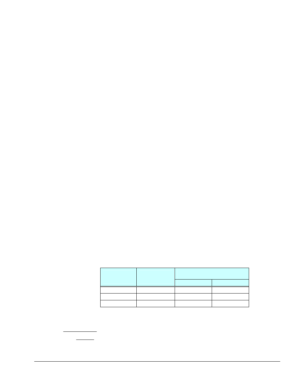
Frequency Response to 5% of
Maximum Output Signal Amplitude
Drive Current
(mA)
Cable Length
@30 pF/ft (Ft)
± 1 V
± 5 V
4
10
550 kHz
110 kHz
4
100
55 kHz
11 kHz
4
1000
5.5 kHz
1.1 kHz
f
K
C
V
Icc Ib
=
−
⎛
⎝
⎜
⎞
⎠
⎟
2
π
Where:
f = Maximum frequency in Hz
K = 3.45 ×10
9
. K is the scale factor to convert Farads to picoFarads and Amperes to milliAmperes and
a factor to allow cable capacitance to charge to 95% of the final charge.
C = Cable capacitance in picoFarads
V = Maximum peak measured voltage from sensor in volts
Icc = Constant current from current source in mA
Ib = Current required to bias the internal electronics, typically 1 mA
ZonicBook/618E
878595
Analog Signals 6-15