Comparator ……7-4, Comparator – Measurement Computing ZonicBook 618E rev.3.4 User Manual
Page 68
Comparator
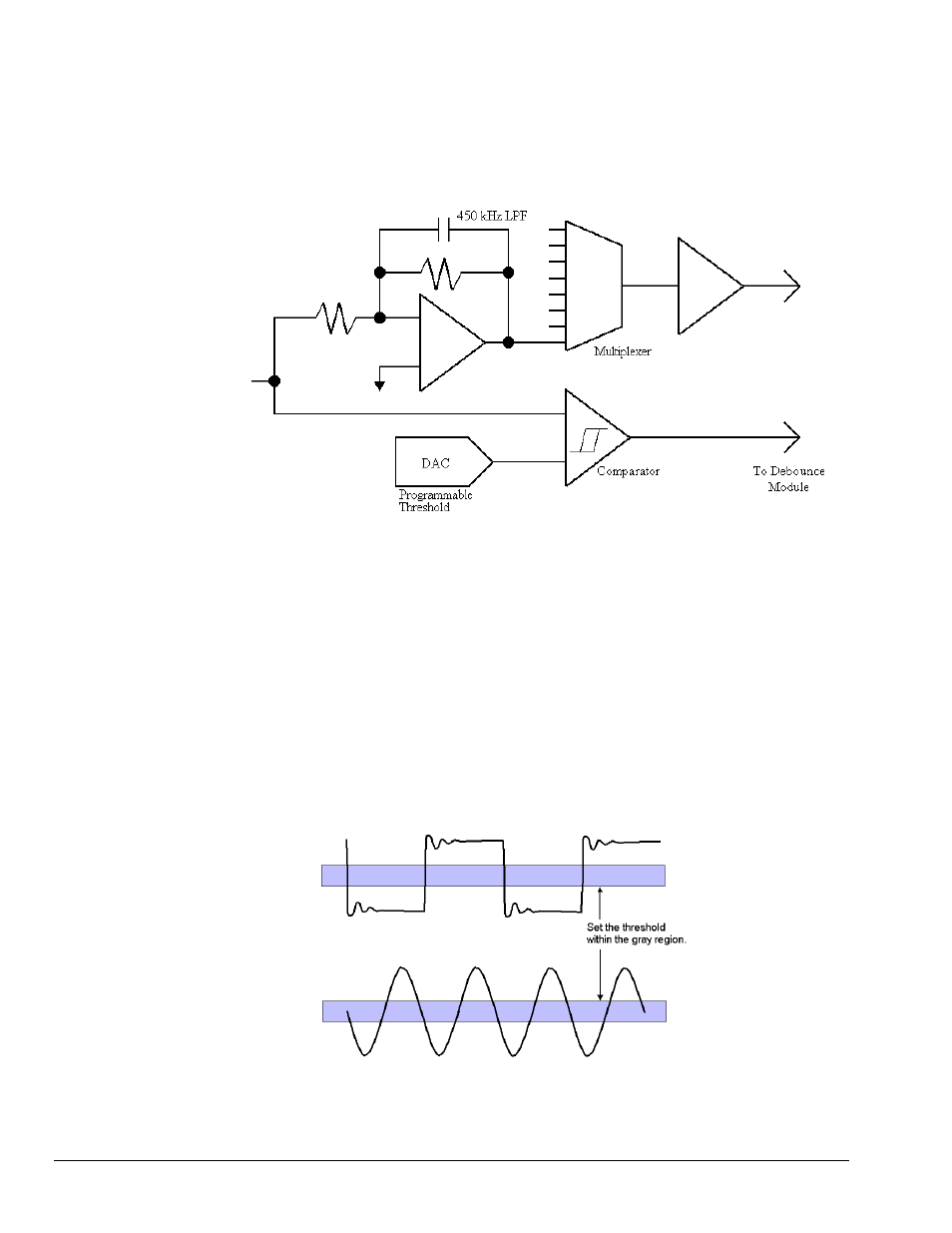
Each channel has its own comparator. The output of the coupling stage feeds the comparator circuit. The
analog waveform that is present at the comparator is gain adjusted and then multiplexed. This allows the
analog input waveform [as it appears at the comparator, post coupling] to be scanned like any other analog
waveform. The analog path is bandwidth-limited to 450 kHz. The analog path between the input and the
comparator is not bandwidth-limited.
To ADC
From
Coupling
Circuit
Comparator
The comparator’s threshold is set by the DAC. The threshold can be set anywhere from -12.5V to +12.5V
in 100mV steps. Since the counter output and analog waveform can be scanned together, the effects of
different comparator switching thresholds can be easily observed. This allows easy adjustment of the
comparator-switching threshold based on input waveform characteristics such as noise and ringing.
The following diagram shows two common input waveforms: a square wave that has some ringing and a
sine wave. The comparator threshold should be set so that the ringing on the square wave does not cause
extraneous switching of the comparator, causing false counts to be measured. Ideally, the comparator
threshold should be set so that the comparator switches at the point of fastest slew rate on the input
waveform. This occurs in the grayed regions of the waveforms.
Amplitude modulated noise may also cause false switching of the comparator. The effects of amplitude
modulated noise can be minimized by setting the threshold at the point of fastest slew rate on the input
waveform. The sine wave shown below has its fastest slew rate within the gray region.
Set the comparator threshold within the gray regions to avoid the effects of ringing and noise.
Setting the Comparator Threshold
7-4 Tach Channels
917695
ZonicBook/618E