Gasboy Fuel Point Vehicle Module User Manual
Page 24
Preparation for Programming
Odometer Ratio (Enter ODO RATIO)
Page 4-10
MDE-4524A Vehicle Module Programming Manual· May 2006
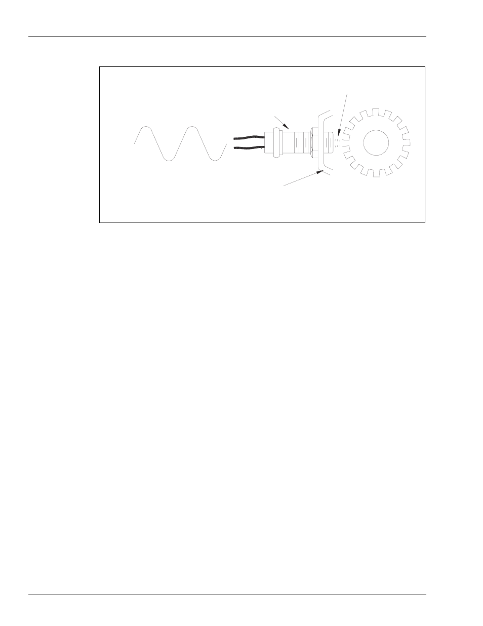
Figure 4-2
SPEEDOMETER
SENSOR
SENSOR
OUTPUT
VOLTAGE
SPEEDOMETER
MAGNETIC
FIELD
TRANSMISSION
Sample Speedometer Circuit
Although there are variations among manufacturers and vehicle types, a typical speedometer
system on a rear-drive-axle vehicle is described here. A gear, usually called the speedometer
signal gear, is mounted to the output shaft of the transmission. The speedometer sensor is
mounted to the transmission so that its tip is in close proximity to the signal gear's teeth. A
permanent magnet located in the speedometer sensor establishes a magnetic field at the tip.
The magnetic field is repeatedly cut by the teeth on the signal gear, creating alternating current
voltage impulses that are transmitted to the speedometer. The frequency and amplitude of the
signal is directly proportional to the speed of the signal gear. The speed of the signal gear is
determined by the rotation of the drive shaft, which is determined by the drive axle ratio and
tire size. Therefore, the number of pulses-per-mile from the speedometer sensor is calculated
from the formula:
# teeth on signal gear X tire revs/mile X drive axle ratio
# of teeth on signal gear is found in the transmission specifications. A typical number of teeth
is 16.
Tire revs per mile can be found in the tire manufacturer's spec sheet. These figures are
standard throughout the tire industry. For example, a new 12.00 R 20 tubeless tire turns 470
revolutions per mile.