Pump control i/o pcb – Gasboy TopKAT Fuel Management System Installation User Manual
Page 93
MDE-4319E TopKAT™ Fuel Management System Installation Manual · August 2008
Page 87
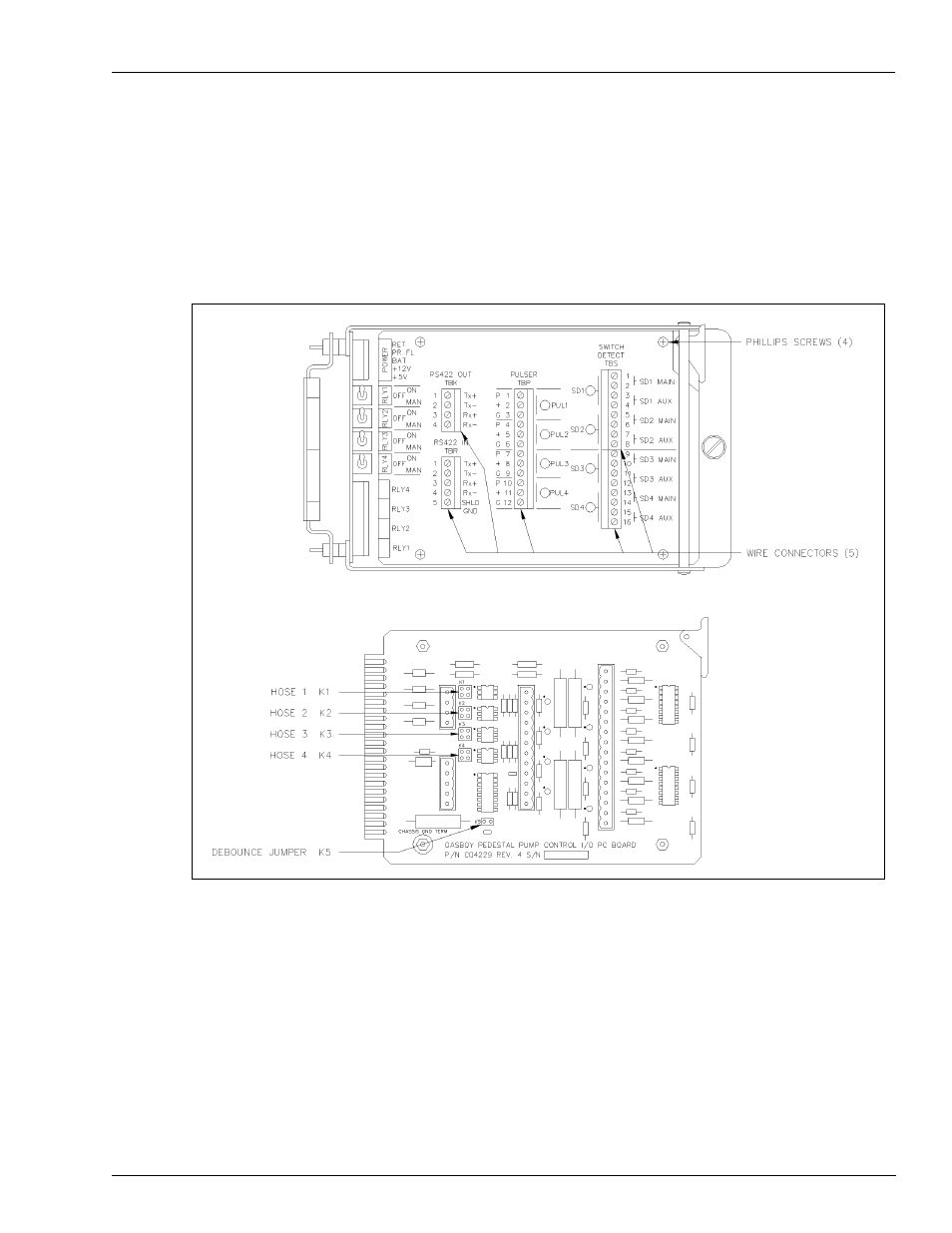
Pump Control I/O PCB
Mechanical PCU Option
Pump Control I/O PCB
The Pump Control I/O PCB, shown in
, consists of two parts, the PCB and a cover
plate. To set the jumpers and switches on the I/O PCB, you must remove all the connectors and
the cover plate.
Figure 8-9: Pump Control I/O Cover Plate and PCB
1
Remove the five green connectors from the front of the Pump Control I/O board.
2
Remove the board from the card cage in the same manner as the EXPMUX Pump Control
CPU board (see step
“Pump Control EXPMUX CPU Board”
on
3
Remove the four Phillips
®
screws securing the cover plate to the PCB and remove the cover
plate.
This manual is related to the following products: