Gasboy TopKAT Fuel Management System Installation User Manual
Page 112
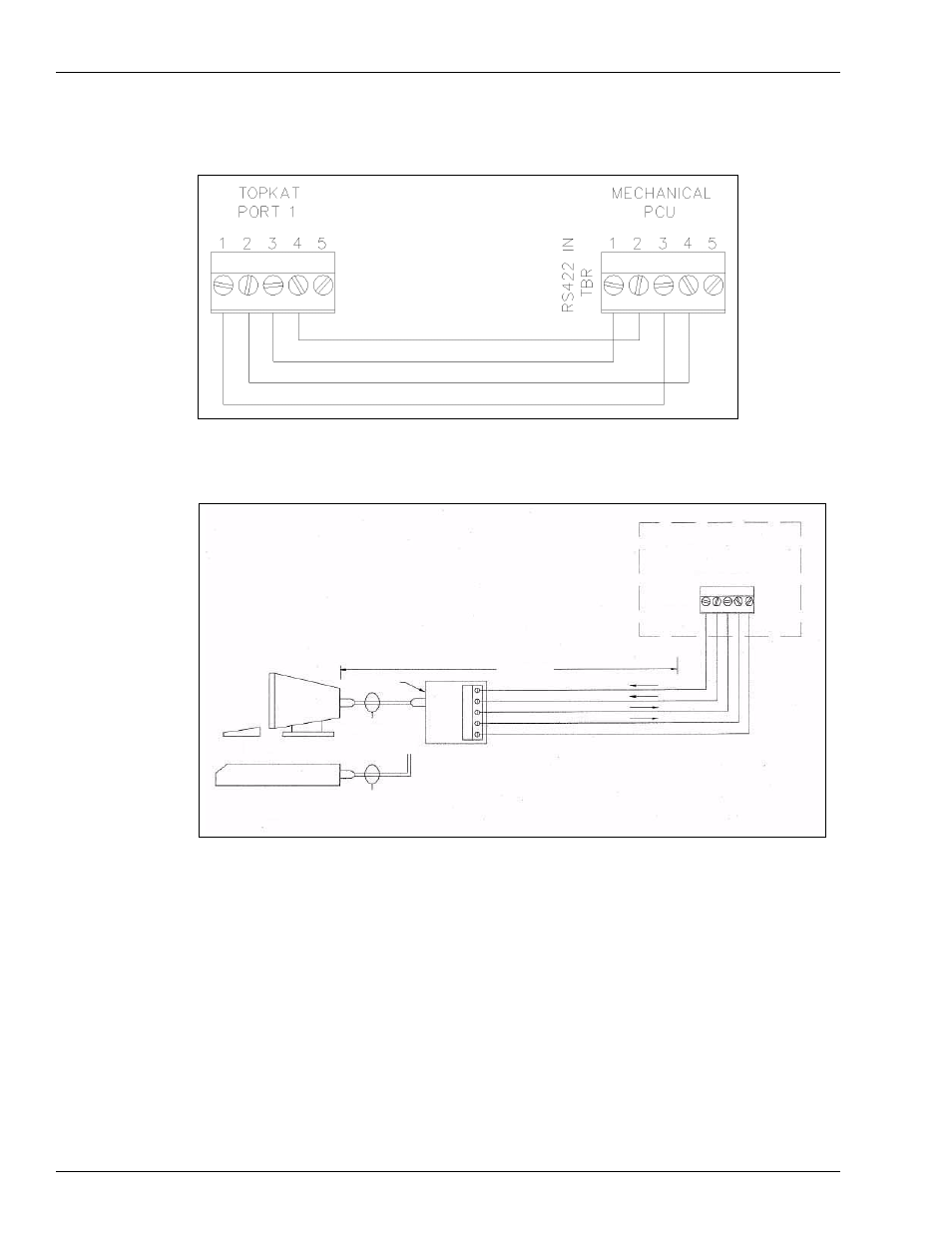
Mechanical PCU Option
Wiring Diagrams: Port Communication
Page 106
MDE-4319E TopKAT™ Fuel Management System Installation Manual · August 2008
Figure 8-22: Wiring Diagram: RS-485 - Communication Cable - TopKAT to Wall-mount
(Remote) Mechanical PCU
Figure 8-23: Wiring Diagram: RS-232 - Gasboy Termination Box
1
1
2
3
4
5
1
2
3
4
5
TopKAT
PORT 2 OR 3
RS-232
100 FEET MAX
P/N C05769
EIA 1:1 CABLE
P/N C04549
MODEM CABLE
P/N C05039
CRT OR PC
ANSWER ONLY
EXTERNAL MODEM
TXD
DTR
RXD
CD
GND
GASBOY
RS-232
Note: In the TopKAT system, the green connector must be connected to P4 on the
communication board for Port 2, and P6 for Port 3. The K1 and K2 jumper for the Port
being used should be set to RS-232. Refer to
location of K1 and K2 jumpers.
This manual is related to the following products: