Gasboy TopKAT Fuel Management System Installation User Manual
Page 113
MDE-4319E TopKAT™ Fuel Management System Installation Manual · August 2008
Page 107
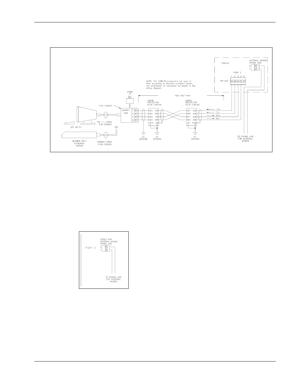
Wiring Diagrams: Port Communication
Mechanical PCU Option
Figure 8-24: Wiring Diagram: RS-422 - Gasboy Short Haul Modem
Notes:1) In the TopKAT system, the green connector must be connected to P3 on the
communication board for Port 2, and P5 for Port 3.
2) In cases where a TopKAT internal modem is used, Port 3 is not available for external
communication wiring.
3) The K1 and K2 jumper for the port being used should be set to RS-422. Refer to
on
for the location of K1 and K2 jumpers.
Figure 8-25: Wiring Diagram: Internal Modem
Notes 1) In cases where a TopKAT internal modem is used, Port 3 is not available for external
communication wiring.
2) The K2 jumper for Port 3 should be removed. Refer to
for the location of the K2 jumper.