Gasboy TopKAT Fuel Management System Installation User Manual
Page 72
Mechanical Interface Option
Wiring Diagrams
Page 66
MDE-4319E TopKAT™ Fuel Management System Installation Manual · August 2008
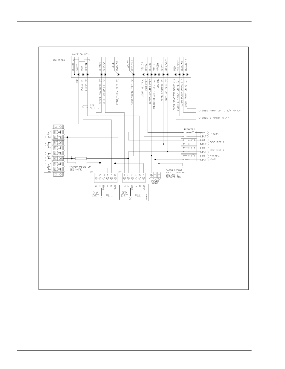
Figure 7-21: Wiring Diagram: 9852XTW1, 9852XTW2, 9853XTW1, 9853XTW2 Dispensers
Diagrams shown are for Q Model pumps. If your pump is an A model, DC Junction box will be separate.
Notes:
1.The power resistor assembly is 8.2 kilo-ohm, 10 W (part number C05818) for 115/230 VAC domestic units and 30 kilo-ohm,
10 W (part number C06683) for 230 VAC International units. Two assemblies required for twins.
2. Before applying power, the TopKAT Pump Control PCB jumpers must be set for electronic pulser as shown in
. Failure to properly set the jumpers will damage the TopKAT.
3. The wire colors may vary. Refer to current pump wiring diagrams.
4. When multiple dispensers are used to control a common submersible starter relay or pump, and the 9800 is controlled
(authorized) through the Control/Subm Feed line (as in the case of some fuel management systems), it is important that the
lines from the 9800 to the submersible equipment be isolated from each other. This can be accomplished by running the
submersible control lines through a secondary set of relay contacts in the fuel management system. If a secondary set of
contacts is not available, external control relays must be used between the 9800 and the submersible starter relay or pump.
Another option is to provide a separate submersible starter relay for each hose outlet. The submersible drive lines from the
9800 cannot be tied together.