Gasboy TopKAT Fuel Management System Installation User Manual
Page 69
MDE-4319E TopKAT™ Fuel Management System Installation Manual · August 2008
Page 63
Wiring Diagrams
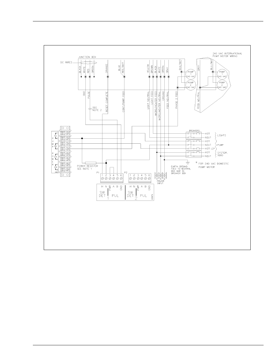
Mechanical Interface Option
Figure 7-18: Wiring Diagram: 9853HC, 9840 Pumps
Diagrams shown are for Q Model pumps. If your pump is an A model, DC Junction box will be separate.
Notes:
1. The power resistor assembly is 8.2 kilo-ohm, 10 W (part number C05818) for 115/230 VAC domestic units and 30 kilo-ohm,
10 W (part number C06683) for 230 VAC International units.
2. Before applying power, the TopKAT Pump Control PCB jumpers must be set for electronic pulser as shown in
. Failure to properly set the jumpers will damage the TopKAT.
3. The wire colors may vary. Refer to current pump wiring diagrams.
This manual is related to the following products: