Wiring diagrams, Pulser wiring notes – Gasboy TopKAT Fuel Management System Installation User Manual
Page 56
Mechanical Interface Option
Wiring Diagrams
Page 50
MDE-4319E TopKAT™ Fuel Management System Installation Manual · August 2008
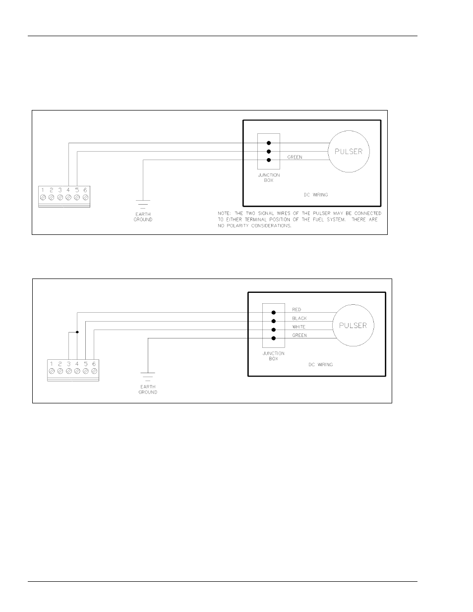
Wiring Diagrams
Figure 7-4: Wiring Diagram: Veeder-Root
®
Reed Switch Pulser, 1871 Series 10:1
Figure 7-5: Wiring Diagram: Veeder-Root Electronic Pulser, 7671 Series 100:1
Pulser Wiring Notes
Notes:1) All the pulsers shown above are connected to Hose 1.
2) Jumpers on the Pump Control PCB must be properly jumpered according to the
pulser type. This must be done by the person performing the start-up. Power to the
system must not be turned on prior to this setup.
3) Refer to
for detailed system installation specifications.
This manual is related to the following products: