Wiring for modems, External modems, Internal modems – Gasboy TopKAT Fuel Management System Installation User Manual
Page 44: External modems internal modems
TopKAT Master/Satellite
Wiring for Modems
Page 38
MDE-4319E TopKAT™ Fuel Management System Installation Manual · August 2008
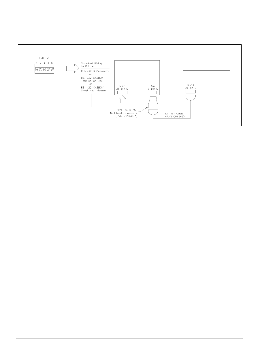
Figure 6-5: Wiring Diagram: CRT Terminal and Okidata Printer
CRT Terminal (M07339B001)
and Keyboard (Q13181-02)
Okidata ML 186 Printer with
Super-speed Serial I/F (Part
Number PA03730000)
*Part Number C03813 is the
combination of M07339B001,
Q13181-02 and C01633
Wiring for Modems
External Modems
The type of phone line required for communication via an external modem is dependant on the
type of modem used and the method of communication desired. Refer to the manual that is
provided with the modem for specific requirements.
Internal Modems
When the TopKAT internal modem is installed, Port 3 communication is routed through the
modem in place of being wired at the DC Junction box. Jumper K2 should be removed. Refer
to
for the location of K1 and K2 jumpers. The phone line for
the internal modem can be installed in the DC conduit. If you install the modem in the DC
conduit, a two twisted-pair shielded cable must be used as specified in
on
and the shield drain wire must be connected to the system AC
ground. Check with your local phone company for proper installation of the phone line.