Comtech EF Data LCS-4 User Manual
Page 37
LCS-4 L-Band Combiner Switch
Revision 1
Low Noise Block Assembly
MN/LCS4.IOM
1. Remove all protective tape from switch
and keep it clean.
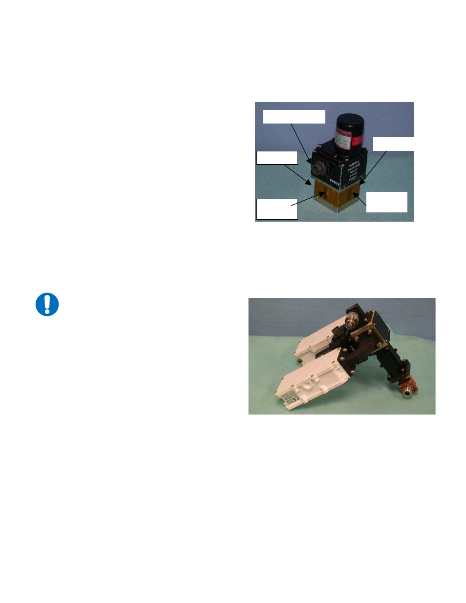
Figure 4-5. Switch Port Locations
2. Position LNBs and gaskets
(GA/GSKTCP75HALF) on Port 2 and
Port 4 of switch.
3. Secure each LNB with eight bolts,
flat washers, and split washers.
4. Position adapter (RF/ADP-WR75-N)
and gasket on Port 3 and secure with bolts,
flat washers, and split washers.
5. Place termination (CN/CX50NMALE)
on threaded port of adapter.
6. Position the customer-furnished TRF filter
and a gasket on Port 4 of the switch.
7. Install the optional support bracket
(FP/BR0085). Secure with eight bolts,
flat washers, and split washers.
8. Set assembly aside for later installation.
IMPORTANT
Ensure that the OUTPUT flange of the filter
is against the switch.
Figure 4-6. Ku-Band LNB Switch
Port 1
Port 2
Port 3
Connector
Port 4
4–9
- CDD-880 (124 pages)
- CDM-800 (130 pages)
- ODMR-840 (184 pages)
- CDM-750 (302 pages)
- CDM-840 (244 pages)
- SLM-5650A (420 pages)
- CTOG-250 (236 pages)
- CDM-700 (256 pages)
- CDM-760 (416 pages)
- CDM-710G (246 pages)
- CDM-600/600L (278 pages)
- CDMR-570L (512 pages)
- CDM-625 (684 pages)
- CDM-625A (756 pages)
- CDD-564A (240 pages)
- CDD-564L (254 pages)
- CLO-10 (134 pages)
- MCED-100 (96 pages)
- CDMR-570AL (618 pages)
- CDM-600 LDPC (2 pages)
- BUC Power Supply Ground Cable (2 pages)
- MPP70 Hardware Kit for CDM-570L (4 pages)
- MPP50 Hardware Kit for CDM-570L (4 pages)
- CDM-625 DC-AC Conversion (4 pages)
- CDM-625 DC-AC Conversion with IP Packet Processor (4 pages)
- DMDVR20 LBST Rev 1.1 (117 pages)
- DMD-2050 (342 pages)
- DMD2050E (212 pages)
- DMD1050 (188 pages)
- OM20 (220 pages)
- QAM256 (87 pages)
- DD240XR Rev Е (121 pages)
- MM200 ASI Field (5 pages)
- DM240-DVB (196 pages)
- MM200 (192 pages)
- CRS-150 (78 pages)
- CRS-280L (64 pages)
- CRS-170A (172 pages)
- CRS-180 (136 pages)
- SMS-301 (124 pages)
- CiM-25/8000 (186 pages)
- CiM-25 (26 pages)
- CRS-500 (218 pages)
- CRS-311 (196 pages)
- CIC-20 LVDS to HSSI (26 pages)