Fault and online status connector, Ault and, Nline – Comtech EF Data LCS-4 User Manual
Page 27: Tatus, Onnector
LCS-4 L-Band Combiner Switch
Revision 1
Connector and Pinouts
MN/LCS4.IOM
3.4 F
AULT AND
O
NLINE
S
TATUS
C
ONNECTOR
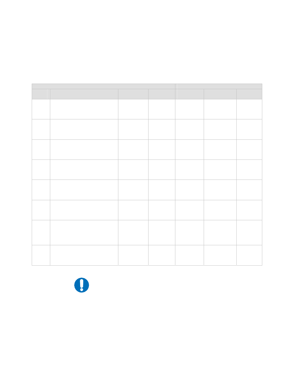
J19, 25-pin D Female, Fault and Online Status.
Pins Connected
Pins
#
Signal Name
Signal
Direction
Type
Fault
Alarm
OK (No
Fault)
Power
Off
2
1
14
BUC1_FLT_NO (BUC A)
BUC1_FLT_COM (BUC A)
BUC1_FLT_NC (BUC A)
I/O Form
C
Form C
Form C
1 - 14
1 - 2
1 - 4
16
15
3
BUC2_FLT_NO (BUC B)
BUC2_FLT_COM (BUC B)
BUC2_FLT_NC (BUC B)
I/O Form
C
Form C
Form C
15 - 3
15 - 16
15 - 3
5
4
17
LNB1_FLT_NO (LNB B)
LNB1_FLT_COM (LNB B)
LNB1_FLT_NC (LNB B)
I/O Form
C
Form C
Form C
4 -17
4 - 5
4 - 17
19
18
6
LNB2_FLT_NO (LNB B)
LNB2_FLT_COM (LNB B)
LNB2_FLT_NC (LNB B)
I/O Form
C
Form C
Form C
18 - 6
18 - 19
18 - 6
8
7
20
SYS_FLT_NO
SYS_FLT_COM
SYS_FLT_NC
I/O Form
C
Form C
Form C
7 - 20
7 - 8
7 – 20
22
21
9
BUC2_ONLINE (BUC B)
BUC_ONLINE_COM BUC A/B)
BUC1_ONLINE (BUC A)
I/O Form
C
Form C
Form C
_
_
9 -21
11
10
23
LNB2_ONLINE (LNB B)
LNB_ONLINE_COM (LNB
A/B)
LNB1_ONLINE (LNB A)
I/O Form
C
Form C
Form C
_
_
10 - 23
12
13
24
25
GND
GND
GND
GND
GND
GND
GND
GND
GND
GND
GND
GND
_
_
_
IMPORTANT
The Fault/Alarm column shows the pins that are connected when a
fault condition exists. The OK column shows the pins connected in
the un-faulted/un-alarm condition. The conditions made when prime
power is disconnected from the unit are shown in the Power Off
column.
3–3