Features, Optional items, Eatures – Comtech EF Data LCS-4 User Manual
Page 18: Ptional, Tems
LCS-4 L-Band Combiner Switch
Revision 1
Introduction
MN/LCS4.IOM
1.3 F
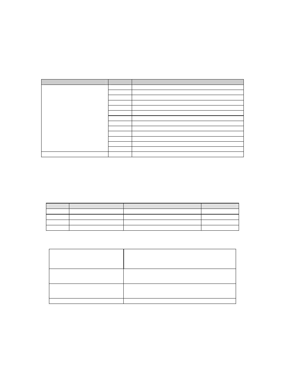
EATURES
Standard FAST, or Hardware
Phase
Description
Combiner, Splitter
Hardware
1
Single or dual AC PS for unit or BUC (options)
Standard 1
L-Band
Splitting/Combining
Standard
1
Flash of all programmable items via Remote RS-232 port
Standard
1
10 MHz External Reference input
Standard
1
Multiple fans and monitoring
Standard
1
BUC FSK control via modem (pass-though)
Standard
1
FSK driver/receiver hardware on RF card.
Standard
1
High temperature Alarm/Internal temperature report.
Standard
1
Front panel LED/Switch Control and Monitoring.
1:1 Switching Capability
1
Hardware support developed in Phase 1.
Standard 1
BUC/LNB
switching
Standard
1
10 MHz sourcing to modems
Note: Separate definition of the ODU/BUC and LNB switches and interconnecting cables are
required for this unit to operate.
1.4 O
PTIONAL
I
TEMS
Option
Unit Power Supply
ODU/BUC Power Supply
Description
0
1 each, Non-redundant AC N/A
Standard
1
2 each, Redundant AC
N/A
Optional
2
2 each, Redundant AC
2 each, 24 VDC 100W Redundant AC
Optional
3
2 each, Redundant AC
2 each, 48 VDC 150W Redundant AC
Optional
The following optional items are needed for this unit to function as a system.
Connector/Cable Assemblies
L-Band IF Cable (Optional)
Outdoor LNB and BUC switch control (Optional)
Modem/Modulator Interconnect
Host (Optional)
ODU/BUC RF Switch Assembly and
Mounting Kits
Ku-Band (Optional)
C-Band (Optional)
Ka-Band (Future) (Optional)
LNB RF Switch Assembly and
Mounting Kits
Ku-Band (Optional)
C-Band (Optional)
Ka-Band (Optional)
PC to FSK BUC Cable
For charging address of BUC.
1–4