Multi-pin connector pinout, Remote port connector, Ulti – Comtech EF Data LCS-4 User Manual
Page 26: Onnector, Inout, Emote
LCS-4 L-Band Combiner Switch
Revision 1
Connector and Pinouts
MN/LCS4.IOM
3.2 M
ULTI
-P
IN
C
ONNECTOR
P
INOUT
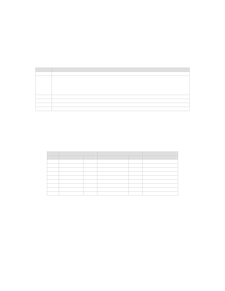
Table 3-2. Multi-Pin Connector Pinout
Ref Des Description
J18
RS-232/485 Remote Port
J19
Online and Fault Status:
Status: Form C contacts ODC/BUC A/B Online and LNB A/B Online
BUC Faults: Form C contacts BUC A and B fault status
LNB Faults: Form C contacts LNB A and B faults status.
Combiner Switch Faults: Form C contacts failed/OK status.
J20
Modulator Fault/TX OFF: Inputs and Mute
J21
BUC/LNB Fault Input: BUC A and B, LNB A and B, Enable BUC Faults, Enable LNB Faults.
J22
LNB RF Switch Driver
J23
BUC RF Baseball Switch Driver
3.3 R
EMOTE
P
ORT
C
ONNECTOR
J18, 9-pin D Male, Remote Port
Table 3-3. Multi-Pin Connector Pinout
RS-232
RS-485
Pin # Signal Name
I/O
Signal Name
I/O
Description
1 GND
GND GND
GND GND
2
RS-232 TD Output
TX Line
3
RS-232 RD Input
RX Line
4
5 GND
GND GND
GND GND
6
RS-485 RX+B Input
RX Line
7
RS-485 RX-A
Input
RX Line Complement
8
RS-485 TX+B Output TX Line
9
RS-485 TX-A
Output TX Line Complement
Note: For RS-485, 2-Wire, half-duplex operation, Pin 7 (RX-A) and Pin 9 (TX-A) are tied
together to form TX/RX -. Similarly, Pin 6 (RX+B) and Pin 8 (TX+B) are tied together to
form TX/RX+.
3–2