Chp3.pdf, System operation, Coaxial connectors – Comtech EF Data LCS-4 User Manual
Page 25: Chapter 3. system operation, Oaxial, Onnectors
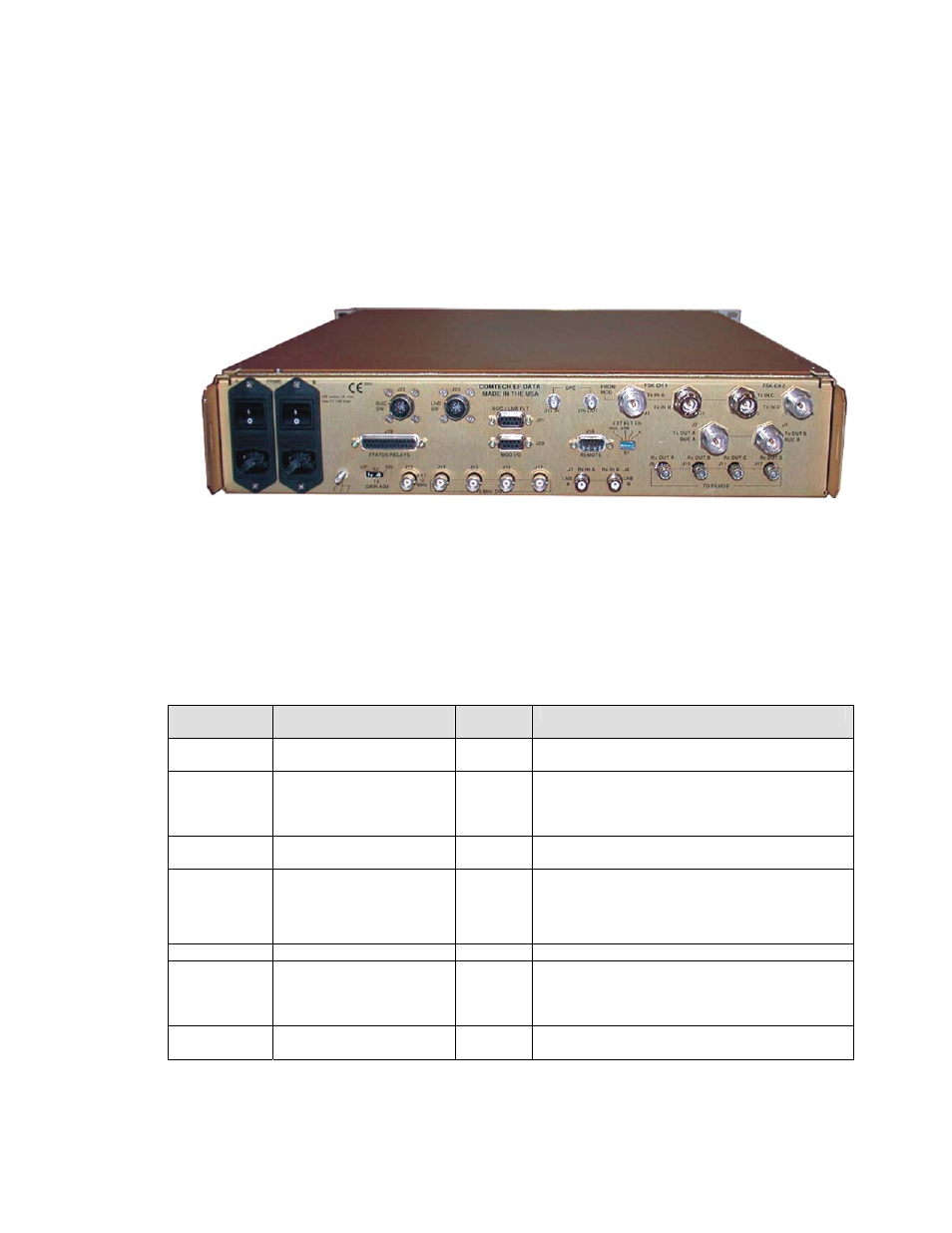
Chapter 3. SYSTEM OPERATION
Figure 3-1. Rear Panel
3.1 C
OAXIAL
C
ONNECTORS
Table 3-1. Coaxial Connectors
Coaxial
Connector
Connector Type
I/O
Description
J1
J2
Type N, Female
Type N, Female
O
O
BUC B L-Band Output
BUC A L-Band Output
J3
J4
J5
J6
Type N, Female
Type N, Female
Type N, Female
Type N, Female
I/O
I/O
I/O
I/O
Modulator 1 L-Band Input, FSK I/O
Modulator 2 L-Band Input
Modulator 3 L-Band Input
Modulator 4 L-Band Input, FSK I/O
J7
J8
Type N, Female
Type N, Female
I/O
I/O
LNB B L-Band Inputs
LNB A L-Band Inputs
J9
J10
J11
J12
Type F, Female
Type F, Female
Type F, Female
Type F, Female
O
O
O
O
Demodulator 1 L-Band Output
Demodulator 2 L-Band Output
Demodulator 3 L-Band Output
Demodulator 4 L-Band Output
J13
BNC, Female
I
External 10 MHz Reference Input
J14
J15
J16
J18
BNC, Female
BNC, Female
BNC, Female
BNC, Female
O
O
O
O
10 MHz Output
10 MHz Output
10 MHz Output
10 MHz Output
J24
J25
SMA, Female
SMA, Female
O
I
TX IF to Uplink Power Control (UPC) (Optional)
TX IF from UPC
3–1